


CDM-Qx Satellite Modem Revision 5
Front Panel Operation MN/CDMQx.IOM
5–4
5.2 Left-Hand Display Area
The left side of the display (or slot screen) efficiently indicates what is in the four plug-in
slots and which slot is currently being addressed.
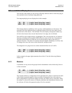
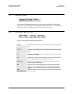
Four ungrouped plug-ins are displayed as in this example:
This display indicates modulators in the top slots, and demodulators in the bottom. The
locations of the four indicators line up with the location of the four slots when viewed
from the back of the chassis. The left hand TX on the display corresponds with the top
left slot in the chassis when viewed from the back. An empty slot is left blank.
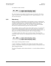
The left RX on the example display is highlighted. This is the selected slot. All monitor
functions (including the front panel LEDs) reflect the status of this slot. All parameters
selected from the menu tree while this slot is selected apply either to this slot or to
common functions. The menus for common functions appear redundantly in all four slots.
To change slots, move the cursor to the desired slot, and press enter.
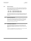
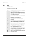
The designator for a plug-in device with an unmasked failure has an F suffix:
In this example, the upper right transmitter has a fault. (View the fault using Monitor,
Alarms, etc).
5.2.1 Modems
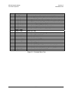
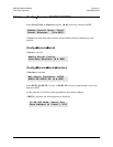
A modulator in a top slot can be grouped with a demodulator in the slot directly below it
to form a modem:
The example indicates a configuration in the right hand slots (when viewed from the back
of the chassis) grouped together to form a modem. Selecting the slots is the same as a
basic configuration except that the blank area below the MD are not be selectable. When
the modem is selected, the menus will display modulator and demodulator functions, and
the software will select the appropriate plug-in for the command.
TX TX | (right hand display area)
<RX> RX | (right hand display area)
TX TXF | (right hand display area)
<RX> RX | (right hand display area)
TX <MD> | (right hand display area)
RX | (right hand display area)