


CDM-Qx Satellite Modem Revision 5
Functional Description MN/CDMQx.IOM
3–2
The RX IF signal is translated and filtered at an intermediate frequency (IF) using the
coarse step synthesizer. This is mixed with a second synthesizer, resulting in the signal
being IF sampled with a high-speed analog to digital converter (A to D). The sampled IF
is then digitally split into an in-phase (I) and a quadrature (Q) component. An AGC
circuit keeps the desired signal level constant over a broad range of input levels. The I
and Q signals are then decimated to reduce the computation rate into the poly phase
matched filter. Carrier and clock recovery is performed on the baseband I and Q signals
after the matched filter. The resultant demodulated signal is fed, in soft decision form, to
the selected FEC decoder (which can be Viterbi, TCM, Reed-Solomon, or Turbo if
installed). After decoding, the recovered clock and data pass to the de-framer (if EDMAC
framing is enabled) where the overhead information is removed. Following this, the data
passes to the Plesiochronous/Doppler buffer, which has a programmable size, or
alternatively bypasses the buffer. From here, the receive clock and data signals are routed
to the terrestrial interface, and are passed to the externally connected DTE equipment.
Physically a modem chassis is comprised of three main card assemblies:
1. The first of these is the IF Backplane card, which includes the frequency
reference; power splitters, power summers, the FSK link and the IF Loop back
functions.
2. The second card is the Digital Back plane card. This routes all the control
signals, the data path switching, the carrier-in-carrier signals and power for all
modules.
3. The third is the M&C, which controls all functions in the unit.
Within the chassis are four slots, which allow any combination of modulators or
demodulators to be installed. If configured as a single modem, two plug-in cards
comprising a modulator and demodulator are required.
A Modulator card contains the transmit interface circuits, the framer, the encoder or
encoders and the signal processing functions of modulation.
A Demodulator card performs all of the signal processing functions of carrier search,
cancellation, demodulation, Forward Error Correction, the de-framer,
plesiochronous/Doppler buffer and the receive interface circuits.
Terrestrial data interface cards can be on the modulator cards or demodulator cards.
When a modulator and demodulator are grouped together, the data interface card can be
used for full-duplex data interface. When 1 up to 4 ports of E1 (with D&I) are needed the
Quad E1 Data Interface Module can be installed in slots 3 and 4.
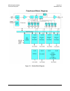
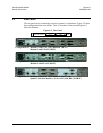
Figure 3-1 shows a functional block diagram of the modem with either modulators and
demodulators in all 4 slots and the figure also shows a modulator in slot 1 and a
demodulator in slot 2 along with a Quad E1 Data Interface Module in slot 3 and 4.