


Instruction Syntax and Addressing Modes
4-14
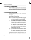
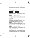
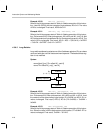
4.3.4 Direct Addressing
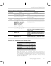
Direct addressing always requires two instruction words. The second word
operand is used directly as the memory address. The memory operand may
be a label or an expression.
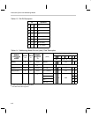
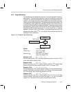
Syntax:
name [dest,] [src,] *dma16 [* 2] [, next A]
name *dma16 [* 2] [, src] [, next A]
Memory Operand
Operand
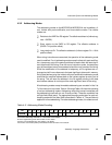
Note the multiplication by 2 with the data memory address. This only needs
to be done for word addresses, i.e., the address that points to 16-bit words.
This is not required for byte addresses. This is explained in detail in section
4.5.
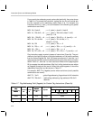
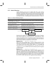
Example 4.3.5 MOV A2, *0x022A * 2
Refer to the initial processor state in Table 4–8 before execution of this instruc-
tion. Loads the contents of data memory location 0x022A (=0x0400) to A2 or
AC11. The MSP50P614/MSP50C614 always accesses data memory as byte
addresses. To read a word address, multiply the address by 2. Final result,
A2 = AC11 = 0x0400.
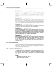
Example 4.3.6 MOV A1~, *0x01F2 * 2, ++A
Refer to the initial processor state in Table 4–8 before execution of this instruc-
tion. Preincrement AP1. After preincrement A1 is AC22 and A1~ is AC6. The
content of data memory location 0x01F2 (=0x12AC) is then loaded to accumu-
lator AC22 (offset of AC6). Final result, AP1=22, AC6 = 0x12AC.
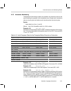
Example 4.3.7 SUB A1~, A1, *0x02A1 * 2, ––A
Refer to the initial processor state in Table 4–8 before execution of this instruc-
tion. Predecrement AP1. After predecrement A1 is AC20 and A1~ is AC4. Sub-
tract the content of 0x02A1 (=0x1001) in data memory from AC20 and store
result to AC4. Final result, AP1 = 20, AC4 = AC20 – 0x1001 = 0x3321 – 0x1001
= 0x2320.
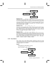
Example 4.3.8 MOV *0x012F * 2, *A0
Refer to the initial processor state in Table 4–8 before execution of this instruc-
tion. This is a table lookup instruction. This instruction reads the program
memory address stored in A0 or AC2 and stores the data in data memory loca-
tion 0x012F. Final result, *0x012F = 0x1B12.
Example 4.3.9 MULR *0x02A1 * 2
Refer to the initial processor state in Table 4–8 before execution of this instruc-
tion. Multiply MR with the contents of 0x02A1. The MSB of the result is stored
in PH register and rounded. The LSB is ignored. Final result, multiply MR •
*0x02A1 = 0x1A15 • 0x1001 = 0x1A16A15, PH = 0x01A1.