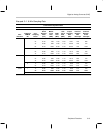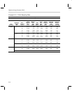
Hardware Initialization States
3-21Peripheral Functions
Note: Internal RAM State after Reset
The RESET low will not change the state of the internal RAM, assuming there
is no interruption in power. This applies also to the interrupt flag register. The
same applies to the states of the accumulators in the computational unit.
When RESET is brought back high again, many of the programmable controls
and registers are left in their default states:
RESET high, just after low . . .
No reference oscillator is enabled. PLL runs at its minimum achievable
rate.
Master clock runs at a very slow frequency (less than 100 kHz).
PLL multiplier is set to 0x00 (renders slowest speed for MC, once
reference is enabled).
RTO oscillator trim bits are set to zero (renders slowest speed for RTO,
once enabled).
Interrupt mask register is 0x00. Global interrupt enable is clear. All
Interrupts are disabled.
I/O Ports A through E and output Port G have the same state as in RESET
low.
All pull-up resistors on input Port F are disabled.
DAC circuitry is disabled (no PDM pulsing).
Both TIMER1 and TIMER2 are disabled. Count-down and period registers
are 0x0000.
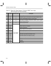
The status register is partially initialized, as specified in Table 3–2.
Idle state clock control and ARM bit are both set to zero.
The processor begins by executing the following steps:
1) ROM block protection word is read from address 0x7FFE.
2) ROM block protection word is loaded to an internal register.
3) RESET interrupt vector is read from address 0x7FFF.
4) Program counter is loaded with the value read from (3); execution re-
sumes there.
Note: Stack Pointer Initialization
The software stack pointer (R7) must be initialized by the programmer, so
that it points to some legitimate address in data memory (RAM). This must
be done prior to any CALL or Ccc instruction. If this is not done, then the first
push/pop operation performed will use the current location pointed to by R7.


