


Instruction Syntax and Addressing Modes
4-13Assembly Language Instructions
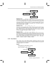
4.3.3 Immediate Addressing
The address of the memory location is encoded in the instruction word or the
word following the opcode is the immediate value. Single word instructions
take one clock cycle and double word instructions take two clock cycles.
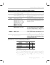
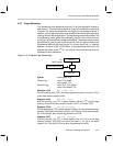
Syntax:
name dest, [src,] imm [, next A]
Where: imm is the immediate value of a 16-bit number.
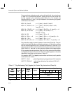
Example 4.3.1 ADD AP0, 0x1A
Assume the initial processor state in Table 4–8 before execution of this instruc-
tion. This instruction adds the immediate value 0x1A to AP0. Final result AP0
= 0x1A + 2 = 0x1C.
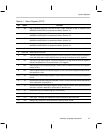
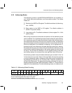
Table 4–8. Initial Processor State for the Examples Before Execution of Instruction
Registers (register# = value)
AP0 = 2 AP1 = 21 (0x15) AP2 = 11 (0x0B) AP3 = 29 (0x1D)
R0 = 0x0454 R1 = 0x0200 R2 = 0x0540 R3 = 0x03E2
R4 = 0x0000 R5 = 2 R6 = 0x03E4 R7 = 0x0100
AC2 = 0x13F0 AC1 = 0x0007 AC17 = 0x0112 AC20 = 0x3321
AC3 = 0xFEED AC28 = 0x11A2 AC29 = 0xAB AC19 = 0x1200
MR = 0x1A15
data memory (*address = data) [word address; to convert to byte, address multiply by 2]
*0x022A = 0x0400 *0x01F2 = 0x12AC *0x02A1 = 0x1001 *0x012F = 0x0000
*0x0100 = 0x0ABC *0x0080 = 0x0000 *0x0001 = 0x499A *0x01FA = 0x0112
program memory (*address = data)
*0x13F0 = 0x1B12
Example 4.3.2 MOV R5, 0xF000
Loads the immediate value 0xF000 to R5 register. Final result, R5 = 0xF000.
Example 4.3.3 MOVB MR, 0xF2
Loads the immediate byte 0xf2 to MR register. Final result, MR = 0xf2.
Example 4.3.4 AND A0, A0~, 0xFF20, ––A
Assume the initial processor state in Table 4–8 before execution of this instruc-
tion. The source accumulator pointer AP0 is predecremented. After predecre-
ment, A0 points to AC1, and A0~ points to AC17. AC17 is anded with the im-
mediate 16-bit value (0xFF20) and the result is stored in AC1. Final result, AP0
= 1, AC1 = 0xFF20 AND AC17 = 0xFF20 AND 0x0112 = 0x0100.