


Instruction Classification
4-22
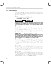
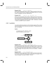
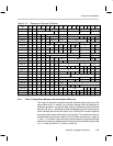
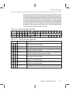
4.4 Instruction Classification
The machine level instruction set is divided into a number of classes. The
classes are primarily divided according to field references associated with
memory, hardware registers, and control fields. The following descriptions
give class-encode bit assignments, the OP code value within the class, and
the abbreviated field descriptions.
Some of the following symbols will be used repeatedly throughout this chapter
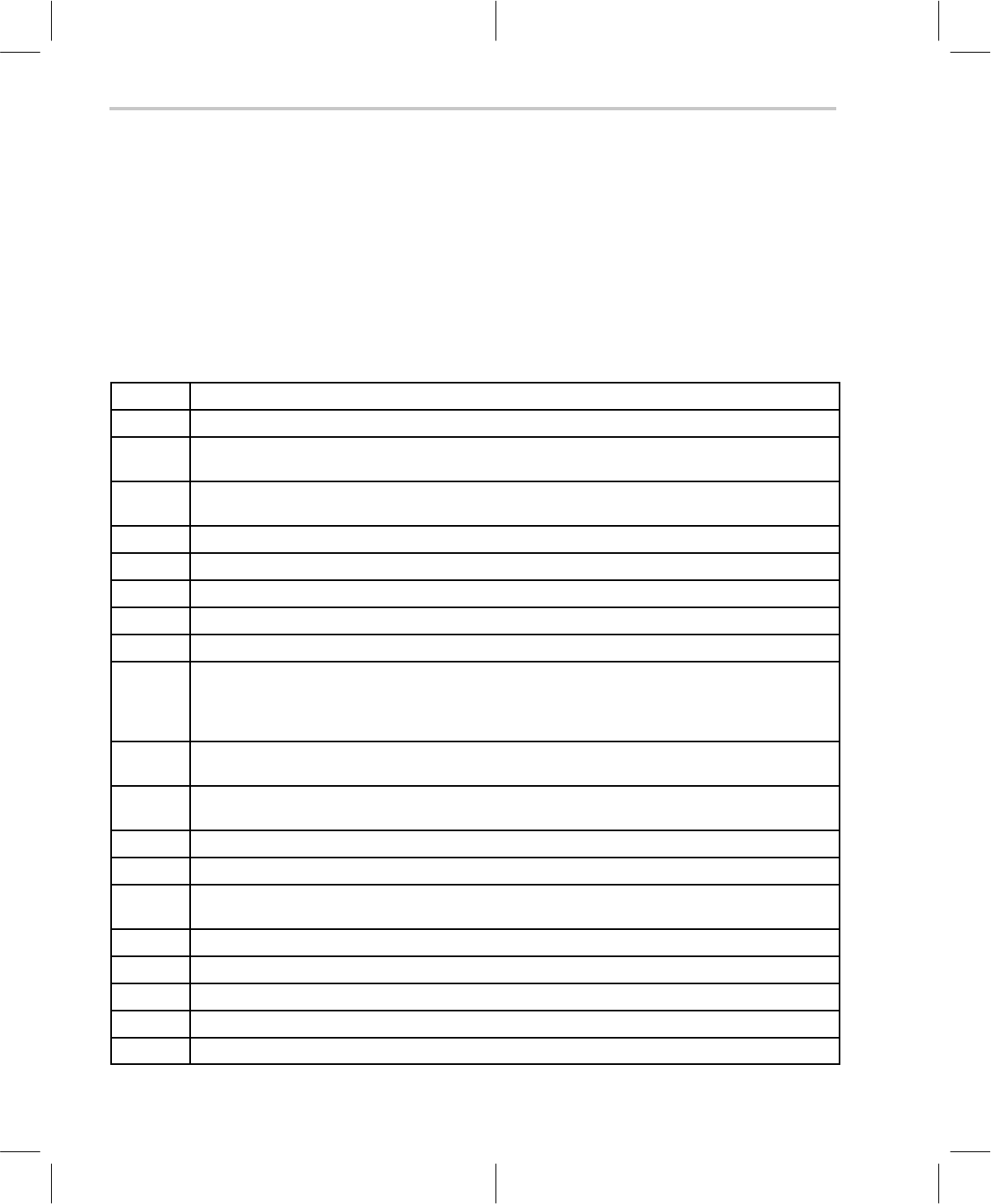
as shown in Table 4–10 (for additional information see section 4.13).
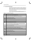
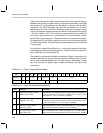
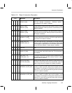
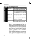
Table 4–10. Symbols and Explanation
Symbol Explanation
! Invert the bit of the source. Used with flag addressing only.
{adrs}
n
The contents of the effective data memory address referred to by the addressing mode syntax. If
n is specified, n bits are involved. If unspecified, data is 16 bits. See Table 4–4.
{cc} Condition code mnemonic used with conditional branch/calls and test flag/bit instructions. Curly
braces indicate this field is not optional.
{flagadrs} Flag addressing syntax as shown in Table 4–7.
~A Select offset accumulator as the destination accumulator if this bit is 1.
~A~ Can be either ~A or A~ based on the opcode (or instruction).
A~ Select offset accumulator as source if this bit is 1.
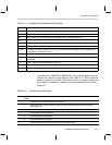
adrs Addressing mode bits am, Rx, pm. See Table 4–4.
An Accumulator pointed to by APn. Accumulators cannot be referenced directly. For example, A22 is
not valid since accumulators are only addressible though the accumulator pointers AP0–AP3.
Therefore, to access accumulators, use A0, A1, A2 and A3. This should not be confused with
APn where AP is an accumulator pointer, not an accumulator.
An~ Indicates the offset of the accumulator pointed to by accumulator pointer An. This is also an ac-
cumulator, not an accumulator pointer.
Apn Accumulator pointer APn where n = 0, 1, 2 or 3. The difference between An and APn is that An is
the accumulator pointed to by APn. In both cases, n ranges from 0 to 3.
cc Condition code bits used with conditional branch/calls and test flag/bit instructions.
clk Clock cycles to execute the instruction
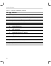
dma[n] n bit data memory address. For example, dma8 means 8–bit location data memory address. If n
is not specified, defaults to dma16.
flagadrs Flag addressing bits as shown in Table 4–7.
flg Test flag bit.
g/r Global/relative flag bit for flag addressing.
imm[n] n bit immediate value
k0...kn Constant field bits.