


Digital-to-Analog Converter (DAC)
3-10
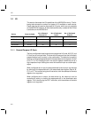
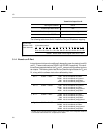
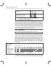
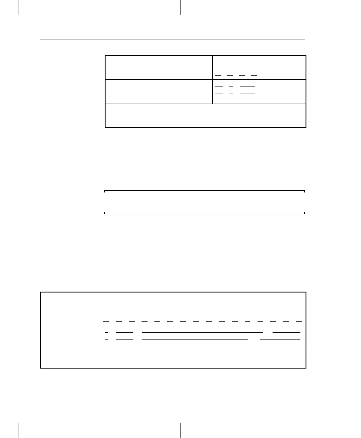
DAC Control register
Address 0x34
(4-bit wide location)
03
02 01 00
Set DAC resolution to 8 bits:
Set DAC resolution to 9 bits:
Set DAC resolution to 10 bits:
DM E 0 0
DM E 0 1
DM E 1 0
DM : Drive Mode selection (0 = C3x style : 1 = C5x style)
E : pulse-density-modulation Enable (overall DAC enable)
0x0 : default state of register after RESET low
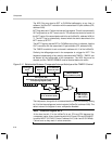
Bit 2 in the DAC control register is used to enable/disable the pulse-density
modulation. This bit must be set in order to enable the overall functionality of
the DAC. After RESET is held low, the default state of bit 2 is clear. In this state,
the output at the DAC pins is guaranteed to be zero (no PDM pulsing). During
DAC activity, the PDM enable bit may also be toggled at any time to achieve
the zero state. In other words, toggling the PDM enable bit from high-to-low-to-
high brings the DAC output to the known state of zero.
Note: PDM Enable Bit
By default, the PDM enable bit is cleared: DAC function is off.
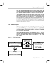
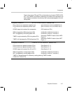
Data values are output to the DAC by writing to the DAC data register, address
0x30. The highest-priority interrupt, INT0, is generated at the sampling rate
governed by the ClkSpdCtrl and the DAC control register. The program in
software is responsible for writing a correctly-scaled DAC value to the DAC
data register, in response to each INT0 interrupt. The register at 0x30 is 16-bits
wide. The data is written in sign-magnitude format. Bit 15 of the register is the
sign bit. Bits 14 and 13 are the overflow bits. Bits 12 through 3 are the
data-value bits: The MSB is bit 12, and the LSB is bit 5, 4, or 3, depending on
the resolution.
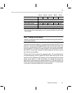
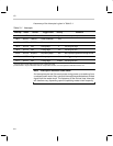
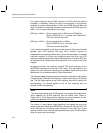
DAC Data register
Address 0x30 (16-bit wide location)
Write Only 15 14 13 12 11 10 09 08 07 06 05 04 03 02 01 00
10 bit DAC resolution:
9 bit DAC resolution:
8 bit DAC resolution:
S OOMDDDDDDDD LXX X
S OOMDDDDDDDL XXXX
S OOMDDDDDDLXXXXX
S : Sign bit M : Most-significant data value D ; Data (magnitude)
O : Overflow bits L : Least-significant data value X : ignored bits
The overflow bits function in different ways, depending on the drive mode
selected. The two DAC drive modes are informally named C3x style and C5x