


I/O
3-6
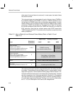
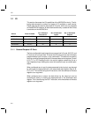
Totem-Pole Output Port G
Data register address
0x2Ch
Possible input data values N/A
Possible output data values 0 = Low 1 = High
Value after RESET low 0 = Low
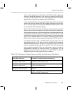
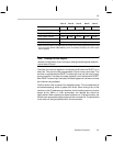
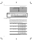
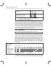
The following table shows the bit locations of the port G address mapping:
G port Data
address 0x2C
read and write
(16-bit wide location)
15
14 13 12 11 10 09 08 07 06 05 04 03 02 01 00
G15 G14 G13 G12 G11 G10 G9 G8 G7 G6 G5 G4 G3 G2 G1 G0
0x0000 : default state of data register after RESET low
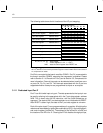
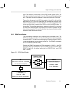
3.1.4 Branch on D Port
Instructions exist to branch conditionally depending upon the state of ports D
0
and D
1
. These conditionals are COND1 and COND2, respectively. The condi-
tionals are supported whether the D
0
and D
1
ports are configured as inputs or
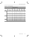
as outputs. The following table lists the four possible logical states for D
0
and
D
1
, along with the software instructions affected by them.
D
0
= 1 COND1 = TRUE. . . CIN1
CNIN1
JIN1
JNIN1
has its conditional call taken.
has its conditional call ignored.
has its conditional jump taken.
has its conditional jump ignored.
D
0
= 0 COND1 = FALSE. . . CIN1
CNIN1
JIN1
JNIN1
has its conditional call ignored.
has its conditional call taken.
has its conditional jump ignored.
has its conditional jump taken.
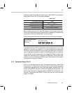
† D
1
= 1 COND2 = TRUE. . . CIN2
CNIN2
JIN2
JNIN2
has its conditional call taken.
has its conditional call ignored.
has its conditional jump taken.
has its conditional jump ignored.
† D
1
= 0 COND2 = FALSE. . . CIN2
CNIN2
JIN2
JNIN2
has its conditional call ignored.
has its conditional call taken.
has its conditional jump ignored.
has its conditional jump taken.
†
COND2 may be associated instead with the comparator function, if the comparator Enable bit
is set. Please refer to Section 3.3, Comparator, for details.