Comparator
3-15Peripheral Functions
3.3 Comparator
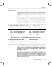
The MSP50C6xx provides a simple comparator that is enabled by a control
register option. The inputs of the comparator are shared with pins PD
4
and
PD
5
. PD
5
is the noninverting input to the comparator, and PD
4
is the inverting
input.
When the comparator is enabled, the conditional operation COND2 (normally
associated with PD
1
) becomes associated with the comparator result. In addi-
tion, the interrupts associated with PD
4
and PD
5
(namely, INT6 and INT7), be-
come interrupts based on a transition in the comparator result. Finally, the
start/stop function of TIMER1 may be controlled, indirectly, by a comparator
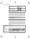
transition. When enabled, the comparator controls the following four events:
(1) Steady-State Comparator TRUE
V
PD5
> V
PD4
COND2 = TRUE . . .
CIN2
CNIN2
has its conditional call taken.
has its conditional call ignored.
JIN2
JNIN2
has its conditional jump taken.
has its conditional jump ignored.
(2) Steady-State Comparator FALSE
V
PD5
< V
PD4
COND2 = FALSE . . .
CIN2
CNIN2
has its conditional call ignored.
has its conditional call taken.
JIN2
JNIN2
has its conditional jump ignored.
has its conditional jump taken.
(3) Comparator transition FALSE-to-TRUE
V
PD5
rises above V
PD4
. . .
INT6 trigger event (If interrupt mask bit, D4, is set)
TIMER1 stops counting (If INT7 flag was set and TIMER1 ENABLE was cleared)
(4) Comparator transition TRUE-to-FALSE
V
PD5
falls below V
PD4
. . .
INT7 trigger event (If interrupt mask bit, D5, is set)
TIMER1 starts counting (If INT6 flag was cleared and TIMER1 ENABLE was cleared)
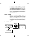
With regards to the transition events, the rising-edge in the comparator is a
trigger for INT6. This happens independently of any activity associated with
TIMER1. TIMER1, on the other hand, can be stopped by a rising edge of the
comparator. The INT7 flag must be set, and the TIMER1 ENABLE must be
cleared before the event.
INT6 flag refers to bit 6 within the interrupt flag register (IFR, peripheral port
0x39). This bit is automatically SET anytime that an INT6 event occurs. This
causes the device to branch to the INT6 vector if the associated mask bit is set
(IntGenCtrl, address 0x38, bit 6). The INT6 flag is automatically CLEARed
when the device branches to the INT6 vector at 0x7FF6. Refer to Section 2.7,
Interrupt Logic, for more details)


