


Instruction Syntax and Addressing Modes
4-18
Example 4.3.20 MOV A3, *R6+0x10
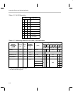
Refer to the initial processor state in Table 4–8 before execution of this instruc-
tion. Load A3 (AC29) with the contents of byte address, R6+0x10. The value
of R6 is unchanged. Final result, AC29=0x0112.
Example 4.3.21 ADD A0~, A0, *R6+0x10, ++A
Refer to the initial processor state in Table 4–8 before execution of this instruc-
tion. Preincrement AP0. After preincrement, A0 is AC3 and A0~ is AC19. Add
AC3 to the contents of byte address R6+0x10 and store the result in AC19. The
value in R6 is unchanged. Final result, AC19 = AC3 + *(R6+0x10) = 0xFEED
+ *0x01FA = 0xFEED + 0x0112 = 0xFFFF.
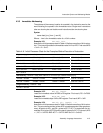
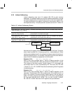
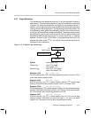
4.3.6.3 Long Relative
Long relative addressing selects one of the 8 address registers (Rx) as a base
value and adds the value of the second word operand. The base address reg-
ister is not modified.
Syntax:
name [dest,] [src,] *Rx+offset16 [, next A]
name *Rx+offset16 [, src] [, next A]
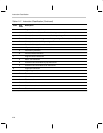
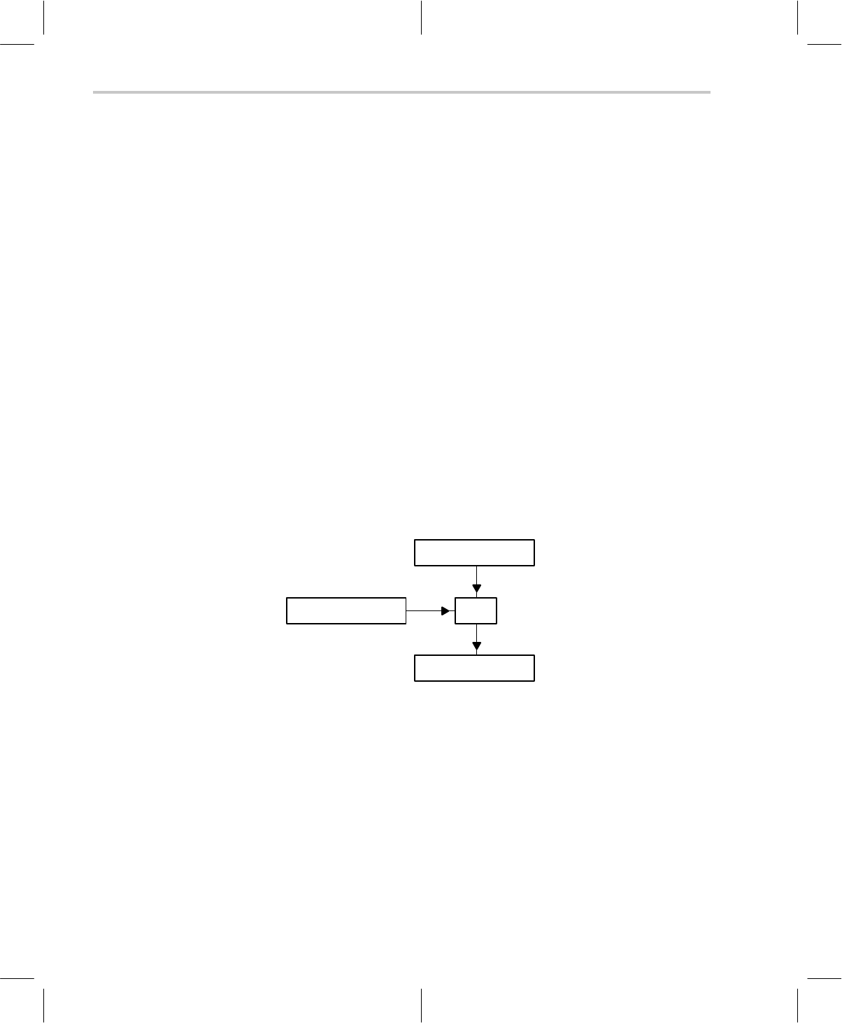
Address
+
Rx
(x = 0 – 7)
Memory Operand
Operand
Example 4.3.22 MOV A0~, *R1+0x0254, ++A
Refer to the initial processor state in Table 4–8 before execution of this instruc-
tion. Preincrement A0. After preincrement, A0 is AC3 and A0~ is AC19. Load
the contents of the data memory byte location R1+0x0254 into AC19. R1 re-
mains unchanged. Final result, AP0=3, AC19=*(R1+0x0254) = *0x022A =
0x0400.
Example 4.3.23 MOV *R7+0x0442, MR
Refer to the initial processor state in Table 4–8 before execution of this instruc-
tion. Store the value in MR to data memory byte location, R7+0x0442. R7 re-
mains unchanged. Final result, *0x02A1 = 0x1A15.