Timer Registers
2-32
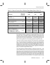
Reading from either the PRD or the TIM returns the current state of the register.
This can be used to monitor the progress of the TIM register at any time.
Writing to the PRD register does not change the TIM register until the TIM
register has finished decrementing to 0x0000. The new value in the PRD
register is then loaded to the TIM register, and counting resumes from the new
value.
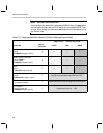
Note: Writing to the TIM Register
Writing to the TIM register causes the same value to be written to the PRD
register. In this case, the TIM register is immediately updated, and counting
continues immediately from the new value.
Each TIMER decrements its count-down register at a fixed clock rate. The rate
is selectable between two existing clock sources: the reference oscillator or
1/2 Master Clock. The rate of the master clock (MC) is programmable. It is
determined by the value loaded to the PLL multiplier (Section 2.9.3, Clock
Speed Control Register). The source to the TIMER is therefore one-half the
frequency of the programmed master clock (1/2 MC). If, instead, the reference
oscillator is selected as the source to the TIMER, then the source is either a
resistor-trimmed oscillator (RTO) or a crystal oscillator (CRO). Both reference
oscillators are designed to run at a nominal 32 kHz. Refer to Section 2.9,
Clock Control, for more information regarding the oscillator configuration and
clock programmability.
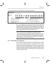
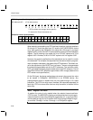
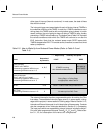
Selection between the timer-source options is made using two control bits in
the interrupt/general control register (IntGenCtrl). The IntGenCtrl is a 16-bit
port-addressed register at 0x38. Clearing bit 8 selects 1/2 MC as the source
for TIMER1. Setting bit 8 selects the reference oscillator as the source for TIM-
ER1. Similarly, clearing bit 9 of the IntGenCtrl selects 1/2 MC as the source for
TIMER2. Setting bit 9 selects the reference oscillator as the source for TIM-
ER2. The default value after a RESET LOW is zero: select 1/2 MC as the
source.
Each of the TIMERs counts from the value stored in its period register to
0x0000. These maximum and minimum counts each receive a full clock cycle
from the TIMER source. This means that the true period of the TIMER, from
one underflow event to the next, is the value stored in the period register plus
one:
Time duration btwn. underflows = (value in PRD + 1) ÷ (frequency of Timer
Source)
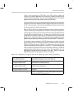
TIMER1 and TIMER2 must be enabled for use. This is done at the IntGenCtrl
register. Bit 10 of the IntGenCtrl is the enable bit for TIMER1, and bit 11 is the


