


Bit, Byte, Word and String Addressing
4-46
Flag Address: The flag (or TAG) address uses linear addressing from 0 to the
size of data memory in 17-bit wide words (0 to 639 for MSP50P614/
MSP50C614). Only the 17
th
bit is accessible. When a word memory location
is read, the corresponding flag for that location is always loaded into the TAG
bit of the status register (STAT). The flag address always corresponds to a
17-bit wide word address. If string instructions are used, then the flag bit of the
last memory location of the string is loaded into the TAG bit of the status regis-
ter. Global flag addressing or relative flag addressing is used to address flags.
Flag bits can be set or reset using flag instructions in addition to various logical
operations. The flag address does not have a string mode.
Rx Post Modifications: Indirect addressing allows post modification of Rx.
For byte and byte-string mode, Rx is post modified by 1 for each byte. For word
and word-string mode Rx is post modified by 2 for each word. Post modification
of Rx is not available for flag addressing.
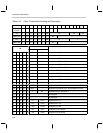
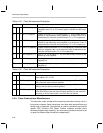
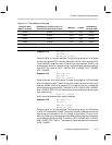
Table 4–40. Data Memory Address and Data Relationship
Mode Address Used Data Order Rx Post modify
†
Single byte Absolute 16-bit address 8-bit data 1
Byte string Beginning of string at lower address String length times 8-bit data
by Incrementing addresses
1 per byte in string
Single word Even address, if odd address is used,
the LSB bit of address is assumed 0
16-bit data 2
Word string Even address beginning at a lower
address; if odd address is used, the
LSB bit of address is assumed 0
String length times 16-bit data
by incrementing addresses
2 per word in
string
Flag Address is considered as holding 17-bit
data, but only 17
th
bit is accessed.
1-bit data not available
†
Rx post modification is available by various addressing modes (see 4.3, Instruction Syntax and Addressing Modes for detail).
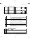
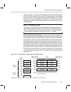
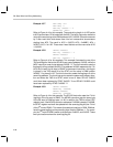
Example 4.5.1 MOVB A0, *0x0003
Refer to Figure 4–4 for this example. This instruction loads the value 0x78 to
the accumulator. The upper 8 bits of the accumulator is padded with zeros.
Example 4.5.2 MOV A0, *0x0000
MOV A0, *0x0001
Refer to Figure 4–4 for this example. Both instructions will load the value
0x1234 to the accumulator. In word addressing, the LSB bit of the address is
assumed to be zero. Thus, in the second instruction, the least significant bit
of the address is ignored.
Example 4.5.3 MOV A0, *0x0004 * 2
Refer to Figure 4–4 for this example. The word address 0x0004 is referred.
Multiplication by 2 is necessary to convert the word address into the equivalent
byte address . After multiplication, the byte address is 0x0008. This instruction
will load the value 0x1122 to the accumulator.