


Interrupt Logic
2-25MSP50C6xx Architecture
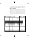
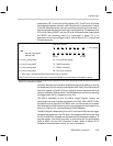
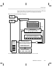
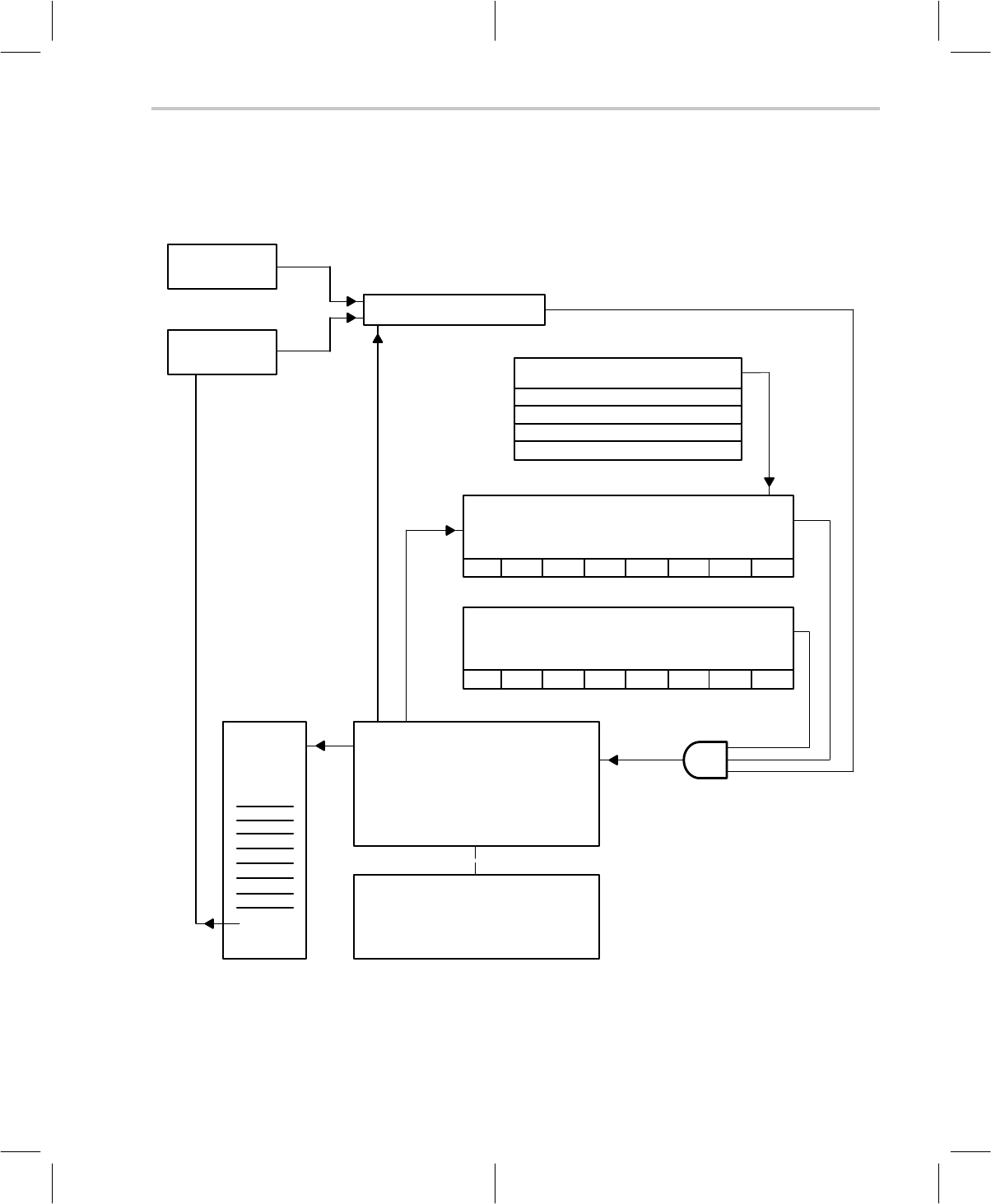
Figure 2–8 provides an overview of the interrupt control sequence. INT0 is the
highest priority interrupt, and INT7 is the lowest priority interrupt.
Figure 2–8. Interrupt Initialization Sequence
INTD
instruction
CLEAR
INTE
instruction
SET
Global Interrupt Enable
CLEAR
• Internal Timer Underflow
• External Input Falling-Edge
• External Input Rising-Edge
• Software Write Instruction
†
Interrupt-Trigger Event
SET BIT
INT Flag bits (IFR)
Associated With the Interrupt-Trigger Event
Interrupt Flag Register (0x39)
INT7 INT6 INT5 INT4 INT3 INT2 INT1 INT0
CLEAR BIT
INT Mask bits (IMR)
Specific Enable for Interrupt Service
Interrupt / General Control Register (0x38)†
INT7 INT6 INT5 INT4 INT3 INT2 INT1 INT0
Interrupt Service Branch
Highest Priority INT is Selected From
Among Those Flagged and Enabled.
Program Branches to Location
Stored in Interrupt Vector.
Interrupt
Service
Routine
(1 of 8)
Interrupt Vector Storage
INTE
IRET
0x7FF0 0x7FF2 0x7FF4 0x7FF6
0x7FF1 0x7FF3 0x7FF5 0x7FF7
†
The port-addressed write instruction (OUT) can be used to SET or CLEAR bits in the IFR and IMR.