


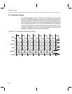

Reduced Power Modes
2-39MSP50C6xx Architecture
Under normal operation the DAC timer, when IMR enabled, triggers an
interrupt on underflow. Before any IDLE instruction, however, the entire DAC
circuitry should be disabled. This ensures the effectiveness of the reduced
power mode and prevents any wake-up from the DAC timer.
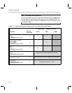
In order to wake the device using a programmable interrupt, the interrupt mask
register must have the respective bit set to enable interrupt service (see Sec-
tion 2.7, Interrupt Logic). In some cases, the ARM bit must also be set, in order
for the interrupts to be visible during sleep.
After the C6xx wakes from sleep, the program counter assumes a specific
location, resuming normal operation of the device. Normally, the destination
of the program on wake-up is the interrupt service routine associated with the
interrupt which initiated the wake-up. The start of the interrupt service routine
is defined by the program location stored in the respective interrupt vector (see
Section 2.6.3, Interrupt Vectors). This wake-up response requires that the
global interrupt enable is set before going to sleep (use the INTE instruction).
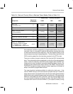
If the global interrupt enable is CLEAR before going to sleep, then the
programmed interrupt can still wake the device, provided that the respective
IMR and ARM bits are set as in Table 2–3. The program counter returns to the
location immediately following the IDLE instruction. This wake-up response
may be useful for putting the C6xx into a hold sleep, where any number of
programmable interrupts can wake the device. To accomplish this, the
appropriate interrupts should be enabled in the IMR. Table 2–6 lists the
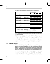
possible destinations of the program counter on wake-up.
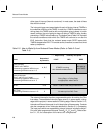
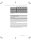
Table 2–6. Destination of Program Counter on Wake-Up Under Various Conditions
State of Interrupt Controls
before IDLE Instruction
Assuming Wake-Up can occur…
Destination of Program Counter after Wake-Up
• Global interrupt enable is SET
• Respective IMR bit is SET
Program counter goes to the location stored in the interrupt vector
associated with the waking Interrupt.
• Global interrupt enable is CLEAR
• Respective IMR bit is SET
Program counter goes to the next instruction immediately following
the IDLE which initiated sleep.
• Global interrupt enable is SET
• Respective IMR bit is CLEAR
Wake-up cannot occur from the programmed Interrupt under these
conditions.
If RESET low-to-high occurs, then program goes to the location
stored in the RESET interrupt vector.