


Comparator
3-16
The INT6 Flag may also be SET or CLEARed deliberately, at any time, in
software. Use the OUT instruction with the associated I/O port address (IFR,
address 0x39).
INT7 flag refers to bit 7 within the interrupt flag register. This bit is automatically
SET anytime that an INT7 event occurs. This causes the device to branch to
the INT7 vector if the associated mask bit is set (IntGenCtrl, address 0x38, bit
7). The INT7 flag is automatically cleared when the device branches to the
INT7 vector at 0x7FF7.
The INT7 Flag may also be SET or CLEARed at any time, in software. Use the
OUT instruction with the associated I/O port address (IFR, address 0x39).
The TIMER1 enable bit is set or cleared in software: bit 10 of the IntGenCtrl.
Similarly, the falling-edge event in the comparator is a trigger for INT7. This
happens independently of any activity associated with TIMER1. TIMER1 can
be started by the falling-edge of the comparator. The INT6 flag must be
cleared, and the TIMER1 ENABLE must be cleared before the event.
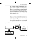
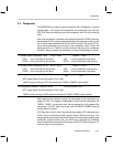
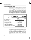
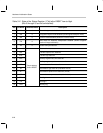
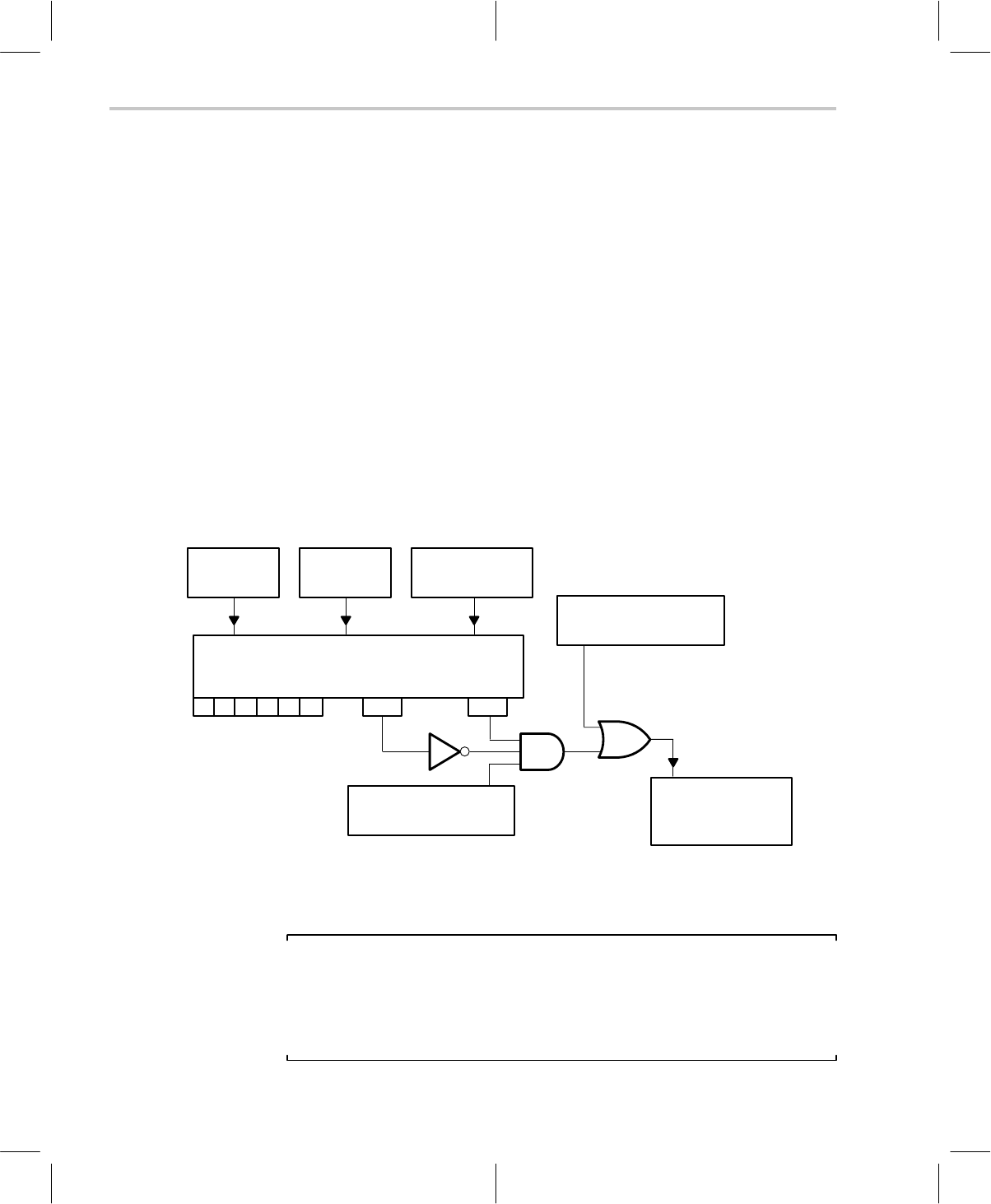
Figure 3–2. Relationship Between Comparator/Interrupt Activity and the TIMER1 Control
INT Flag bits (IFR)
Associated With the Interrupt-Trigger Event
Interrupt Flag Register (0x39)
0 1 2 3 4 5 INT6 INT7
INT-Trigger
Event
INT Service
Branch
port-addressed
write instruction
Comparator ENABLE
Bit 15, IntGenCtrl (0x38)
TIMER1 ENABLE
Bit 10, IntGenCtrl (0x38)
TIMER1 Control
0 = TIM1 stopped
1 = TIM1 running
The comparator, along with all of its associated functions, is enabled by setting
bit 15 of the interrupt/general control register (IntGenCtrl, address 0x38). The
default value of the register is zero: comparator disabled.
Note: IntGenCtrl Register Bit 15
At the time that bit 15 in the IntGenCtrl is set, PD
4
and PD
5
become the
comparator inputs. At any time during which bit 15 is set, PD
4
and PD
5
MUST
be set to INPUT (I/O Port D Control, address 0x1C, bits 4 and 5 CLEARed).
Failure to do so may result in a bus contention.