MSP50P614/MSP50C614 Computational Modes
4-49Assembly Language Instructions
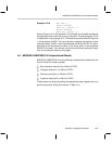
Example 4.5.10 MOV STR, 0
SFLAG *0x00032
MOVS A0, *0x0031 * 2
RFLAG *0x00032
MOVS A0, *0x0031 * 2
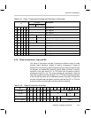
Refer to Figure 4–4 for this example. This example is to illustrate the effect of
the tag/flag bit when used with a string instruction. The string register (STR)
is loaded with 0 (string length of 2). The second instruction sets the flag bit to
1 at flag address 0x0032. The next instruction reads the word-string at word
memory location, 0x0031, into A0 and also sets the TAG bit of STAT to 1 corre-
sponding to the last memory location of the string (which is word address
0x0032 in this case). The next two instructions verify this by setting the flag to
zero and reading the memory string again.
4.6 MSP50P614/MSP50C614 Computational Modes
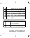
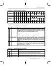
MSP50P614/MSP50C614 has the following computational modes which are
the first 4 bits of the status register.
Sign extension mode (bit 0 or XM bit of STAT)
Unsigned mode (bit 1 or UM bit of STAT)
Overflow mode (bit 2 or OM bit of STAT)
Fractional mode (bit 3 or FM bit of STAT)
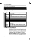
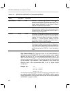
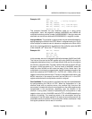
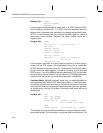
These modes can be set by setting the appropriate status register bits or by
special instructions (Class 9) as shown in Table 4–41.


