


Mechanical Information
7-2
7.1 Mechanical Information
The MSP50C614, MSP50C605, and the MSP50C601 are normally sold in die
form, but are also available in a 100-pin QFP package. The MSP50C604 is a
available in die form and in a 64-pin QFP package. The MSP50P614 is
available in a 120-pin, PGA-windowed ceramic package.
NOTE: Scan Port Bond Out
The scan port interface on the MSP50C6xx devices has five dedicated pins
and one shared pin that need to be used by the MSP50Cxx code
development tools. The SCANIN, SCANOUT, SCANCLK, SYNC, and TEST
pins are dedicated to the scan port interface. The RESET
pin is shared with
the application. These pins may play an important role in debugging any
system problems. For this reason, these pins must be bonded out on any
MSP50C614 production board. Furthermore, it is recommended that these
pins be connected to test points, so the development tool can be connected.
Since the development tool requires V
DD
and V
SS
, test points connected to
these signals are also needed.
The application circuits appearing in section 6.1 show the minimum
recommended configuration for any MSP50C614 application board. For
production purposes, the 1-kΩ resistor which appears at the RESET
pin is
optional. It is required for use with the scan port interface, but they may be
shorted otherwise. The footprints for this resistor are strongly recommended.
7.1.1 Die Bond-Out Coordinates
Die bond-out coordinates are available upon request from Texas Instruments
(email: speak2me@list.ti.com).
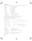
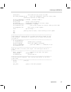
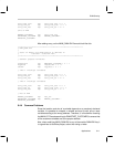
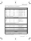
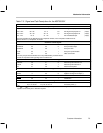
7.1.2 Package Information
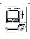
The MSP50C614, MSP50C605, and the MSP50C601 are available in the
100-pin QFP package. See Figure 7–1 and Tables 7–1 thru 7–3. The
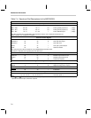
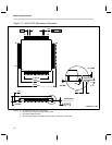
MSP50C604 is a available the 64-pin QFP package. See Figure 7–2 and
Table 7–4. For more detailed information, please refer to the device
datasheets available on the TI speech web site (http://www.ti.com/sc/speech).