


Reduced Power Modes
2-36
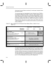
Note: Idle State Clock Control Bit
If the idle state clock control bit is set and the ARM bit is clear, the only event
that can wake the C6xx after an IDLE instruction is a hardware RESET low-
to-high. When at sleep, the device will not respond to the input ports, nor to
the internal timers.
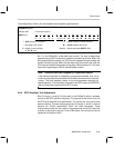
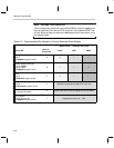
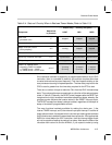
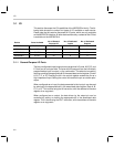
Table 2–3. Programmable Bits Needed to Control Reduced Power Modes
→ deeper sleep … relatively less power →
Control Bit
Label for
Control Bit
LIGHT MID DEEP
Idle state clock control
bit 10
ClkSpdCtrl register (0x3D)
A 0 1 1
Enable reference oscillator
bit 09 : CRO or
bit 08 : RTO
ClkSpdCtrl register (0x3D)
B 1 1 0
ARM
bit 14
IntGenCtrl register (0x38)
C 0 1 1
Enable PDM pulsing
bit 02
DAC Control register (0x34)
D Should be cleared before any IDLE instruction.
IDLE instruction
(executes the mode)
E Same instruction is used to engage any of the modes.
PLL multiplier
bits 07 through 00
ClkSpdCtrl register (0x3D)
F Programmed value is 0 … 255 .