


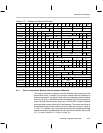

Instruction Syntax and Addressing Modes
4-21Assembly Language Instructions
However, xFLAG instructions use {flagadrs} addressing modes. This includes
global (dma6) and relative (R6 + 6–bit offset). Both take only one clock cycle.
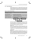
Possible sources of confusion: Consider the following code,
ram0 equ0x0000 *2 ;RAM word zero
ram1 equ0x0001 *2 ;RAM word one
ram2 equ0x0002 *2 ;RAM word two
STAG *ram1
MOV A0,*ram1 ;TAG bit is set in STAT register
RTAG *ram1
SFLAG *ram1 ;This sets the TAG bit of ram2!
MOV A0,*ram1 ;TAG bit is not set in STAT register!
MOV TF1,*ram1 ;TF1 bit in STAT is set!?
Explanation: The first three instructions perform as you would expect. The
TAG bit is set at the RAM variable, ram1. The TAG bit is set in the STAT register
when the MOV instruction executes. Finally, ram1’s TAG bit is cleared.
The next two instructions are problematic. When SFLAG sets the tag bit, it will
set the tag bit for the second word location, ram2. This does not set the TAG
bit for ram1. What is worse is that the value in ram1 must be less than 64
(dma6) since this is global addressing for SFLAG. To access TAG bits for high-
er RAM, the R6 (PAGE) register is needed.
The last instruction is also confusing. Why is TF1 set in the STAT even though
ram1’s TAG bit is not set? The answer is that this MOV instruction considers
the {src} argument to be a word value instead of the usual byte value. Thus,
this MOV instruction operates on ram2 rather than on ram1.