


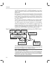

Comparator
3-17Peripheral Functions
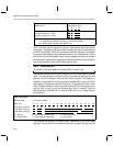
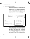
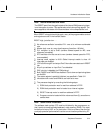
The function of pins PD
4
and PD
5
, and the behavior of events COND2, INT6,
INT7, and TIMER1 are different, depending on whether the comparator has
been enabled or disabled. A summary of the various states appears in the fol-
lowing table:
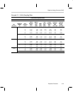
Comparator ENABLED
SET bit 15 in the IntGenCtrl, address 0x38 . . .
PD
4
functions as comparator negative input
PD
5
functions as comparator positive input
(port D Control, 0x1C, bit 4 MUST be 0)
(port D Control, 0x1C, bit 5 MUST be 0)
COND2 maps to the state of the comparator (PD
5
relative to PD
4
)
INT6 is triggered by PD
5
rising above PD
4
INT7 is triggered by PD
5
falling below PD
4
(IntGenCtrl, 0x38, bit 6 must be 1)
(IntGenCtrl, 0x38, bit 7 must be 1)
TIMER1 may be started by PD
5
rising above PD
4
TIMER1 will be stopped by PD
5
falling below PD
4
(assuming TIMER1 Enable is 0 and INT6
flag is 0)
(assuming TIMER1 Enable is 0 and INT7
flag is 1)
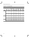
Comparator DISABLED
CLEAR bit 15 in the IntGenCtrl, address 0x38 . . .
PD
4
functions as a general-purpose I/O pin
PD
5
functions as a general-purpose I/O pin
(See Section 3.1.1)
(See Section 3.1.1)
COND2 maps to the state of the I/O pin PD
1
(See Section 3.1.4)
INT6 is triggered by a rising edge at PD
4
INT7 is triggered by a falling edge at PD
5
(IntGenCtrl, 0x38, bit 6 must be 1)
(IntGenCtrl, 0x38, bit 7 must be 1)
TIMER1 is started/stopped in software by setting/clearing TIMER1 enable
(IntGenCtrl, 0x38, bit 10)