


AMD Confidential
User Manual November 21
st
, 2008
114 Chapter 7: Device Configuration
XTRNB: Setting event trigger delay for CPU0[DMAW] to 1205
Logged during execution. DMAW event is setup to be triggered at a later point. 1205 is
the difference between NOW and event time.
XTRNB: Processing queued event CPU0[DMAW] ICount=8403 ShellICount=8403.
Logged during execution. Trigger for event setup earlier is invoked. CPU0 and DMAW
could have different values depending on which CPU it is (MP-XTR only) and which
event is processed.
Interfaces
XTRNB has eight CPU interfaces and an IO Interrupt / APIC interface to connect to the
AweSim‟s CPU Bus and IO Interrupt / APIC interface respectively. For XTR-UP, only
one CPU interface may be used.
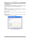
7.22.2 XTR Structure
7.22.2.1 XML Structure
XTR is a text file that contains XML elements for initialization elements, events and
instructions. The XML schema or DTD is not formally defined. XTR XML contains an
Initialization section followed by events and instruction sections. Last event in the XML
must be an EOT event indicating the end of trace. Some XTR elements are explained
below. Please refer to Section 7.22.5, “Example XTR XML File”, on page 117, or the
exact and complete structure of the XTR XML.
All values in the XML are in hexadecimal except for ICount and Length values which are
always in decimal. Exceptions will be stated as necessary.
<Init Device="DIMM" Type="MEMI" Size="536870912" />
Memory initialization (MEMI) information from and for the DIMM device. The value for
"Size" attribute the size of DIMM in bytes in decimal (base 10). Note that this does not
require that XTR playback to have a DIMM device
<Init Device="MEM" Type="MEMI"
File="c:\simnow\xtr\DivergenceAt324303\test_snapshot_3dmarkwof_0.bin" />
Memory initialization file. File path may be relative to the current path.
<Init Device="CPU0" Type="CPU" Item="ICount" Data="227"/>
Initial instruction count in decimal. Different CPUs can have different initial ICounts.
<Init Device="CPU0" Type="CPU" Item="ModeFlags" Data="00000001"/>
The upper 32 bit of ModeFlags must contain Execution Control flags. Please refer to
Section 7.22.3, “ModeFlags”, on page 116 for more information.
<Init Device="CPU0" Type="SREG" Item="TSC" Data="0000000000000000"/>
The initialization information for MSRs. Note that initialization information for TSC will
be ignored. Please use M00000010 for writes to TSC
<Init Device="CPU0" Type="APIC" Length="1024" >