


AMD Confidential
User Manual November 21
st
, 2008
32 Chapter 3: Graphical User Interface
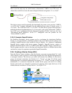
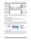
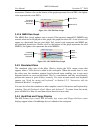
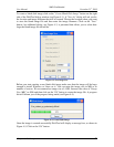
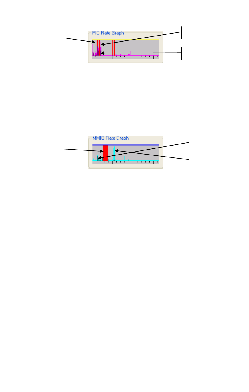
instructions. Darker color on the bottom of the graph represents the read PIO's, the lighter
color represents the write PIO‟s.
Figure 3-21: CPU PIO Rate Graph
3.4.2.6 MMIO Rate Graph
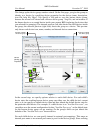
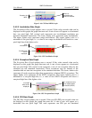
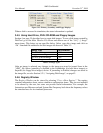
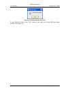
The MMIO Rate Graph updates once a second. If the memory-mapped I/O (MMIO) rate
exceeds what can be displayed on this graph, the graph line turns red. A rate of zero will
appear as a horizontal line one pixel high. Full vertical scale represents one MMIO per
ten simulated instructions. Darker color on the bottom of the graph represents the read
MMIO's, the lighter color represents the write MMIO's.
Figure 3-22: CPU MMIO Rate Graph
3.4.3 Simulated Video
The simulated video area of the Main Window depicts the VGA output screen that
appears when a VGA device is added to the workspace. When the mouse focus is over
the video area, the simulator captures host keyboard input, enabling you to type most
keyboard entries on your real keyboard. This is a convenience and may not accurately
position the mouse or grab all keys correctly. For more accurate mouse and keyboard
capture, see “Grab the mouse and keyboard” in Section 5.2.3, “Interaction with the
Simulated Machine”, on page 45.
You can also allow the simulator to take complete control of the mouse and keyboard by
selecting “Special Keyboard→Grab Mouse and keyboard”. To return from this mode,
press and hold Ctrl then Alt, and then release them in reverse order.
3.4.4 Hard Disk and Floppy Display
The IDE Primary byte counts, IDE Secondary byte counts, and Floppy disk byte counts
displays appear when a Southbridge device is added to the workspace.
Exceeded
what can be
displayed.
Write PIO’s.
Read PIO’s.
Exceeded
what can be
displayed.
Read
MMIO’s.
Write
MMIO’s.