


AMD Confidential
User Manual November 21
st
, 2008
130 Chapter 7: Device Configuration
7.25 Plug and Play Monitor Device
The Plug and Play Monitor device (PnP Monitor) conforms to the VESA Plug and Play
Monitor specification and therefore supports the DDC2B standard. DDC (Display Data
Channel) is the Plug and Play standard for monitors. DDC monitors are designed to meet
the VESA (Video Electronic Standards Association) standard that defines the DDC
implementation. If the video card also supports the DDC standard it gets from the PnP
monitor device all the information about its features and makes consequently an
automatic configuration for the best refresh values depending on the selected resolution.
The Plug and Play monitor device supports the DDC1 and DDC2B standards. DDC1 is
primitive and a point to point interface. The monitor is always put at transmit-only mode
(DDC1). The monitor will continuously transmit data until the monitor will be turned off
or switched to the bi-directional mode (DDC2). In DDC2 mode the I
2
C protocol is being
used for data transfers.
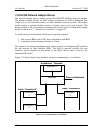
Interface
The Plug and Play Monitor device model has a VGA and DVI interface connection.
Connections can be only made to the VGA or DVI interface. It can be connected to the
VGA or DVI connection of a video card device.
Contents of a BSD
The current state of all internal registers and any internal state variables are saved in the
BSD.
Initialization and Reset State
When first initialized or reset the Plug and Play Monitors DDC registers are set to their
default state. After initialization the monitor device will operate in DDC1 mode. The
device will remain in the DDC1 mode until there is a valid HIGH to LOW transition on
the SCL pin, when it will switch to DDC2B mode.
Differences from Real Hardware
The model attempts to match the functionality of the physical devices from a
programmer's perspective. Upon power-up, a “real” Plug and Play monitor will output
valid data only after it has been initialized. During initialization, data will not be available
until after the first nine clock cycles are sent to the device. This Plug and Play monitor
device model does not simulate this behaviour. It will always output valid data.
The Page Write, Acknowedge Polling, and the Write Protection feature are currently not
supported.
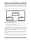
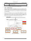
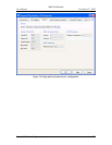
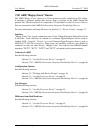
Configuration Options
The Plug and Play Monitor device gives you the opportunity to choose from different
Plug and Play Monitor device models, as shown in Figure 7-35.