


AMD Confidential
User Manual November 21
st
, 2008
Appendix A 177
A Appendix
A.1 Format of Floppy and Hard-Drive Images
The floppy-disk format assumes a standard 1.44 Mbyte floppy disk, consisting of 80
cylinders, 2 heads, and eighteen 512-byte sectors per head (36 sectors per cylinder). The
image file consists simply of each sector, starting with the first sector of the first cylinder
on the first head, and proceeding sequentially through the last sector of the last cylinder
on the second head. The total size of the image file is identical to the total capacity of a
1.44 Mbyte floppy disk, or 1,474,560 bytes.
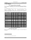
The hard-disk image is formatted in a similar fashion, with the exception that the total
number of cylinders, heads, and sectors per head varies. Because of this, the hard-disk
image file contains a 512-byte header before the raw data. This 512-byte header is
identical to the information provided by the drive in response to the ATA command
"IDENTIFY". Following the 512-byte header is the data for each sector from the device.
As with the floppy, the data starts with the first sector of the first cylinder on the first
head. Unlike floppies, however, the image file may end before the last sector of the last
cylinder on the last head. If an attempt is made by the simulator, to access data on the
drive image that is beyond the end of the available data (but still within the bounds
defined by the geometry of the device), the simulator will extend the image file
dynamically.
The BSD file contains the contents of all Viper Plus registers. It also saves the contents of
any buffers and the states of all internal devices (HDD controllers, PIT, PIC, etc.). When
the BSD file is read in, all buffers are filled with past data, and all states are restored to
their saved states.
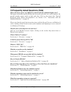
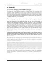
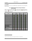
The symbol files that the debugger uses are in a simple text format. Each line contains an
address, length, and symbol name. Any line that starts with a semicolon is considered a
comment. Following is a sample file:
; SimNow Debugger Symbol File Format
;
; Address Length Symbolic Name
004011f0 3f _main
00401a3c 0 _GetModuleHandleA@4
00401a42 0 _GetCommandLineA@0
The address value may be an absolute address or a module-relative address. For the latter
case, the load address may be specified when the symbols are loaded into the debugger
with the "load_symbols" command (see Section 10.2, “Debugger Command Reference”,
on page 151).