


AMD Confidential
User Manual November 21
st
, 2008
Chapter 14: BIOS Developer‟s Quick Start Guide 169
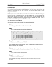
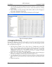
3. Select the tab for the DIMM slot that you wish to alter.
4. Select an SPD byte description from the large list box. The corresponding data
byte will be shown as two hex digits in the small edit box to the right of the list
box.
5. Type a new hex value in the edit box.
6. Optionally, the altered SPD data can be saved to a file by clicking the Export SPD
button.
7. Click OK to close the configuration property sheet and accept the changes.
If the contents of SPD byte 0 (Number of SPD Bytes Used) is set to zero, the DIMM will
not respond to any SMBUS accesses. This allows simulation of a DIMM module that
does not include an SPD ROM.
14.4 Clearing CMOS
View the Devices Window and double-click on the Southbridge. Choose the “CMOS”
tab.
1. Save the current CMOS to disk and call it “blank.cmos”.
2. Open the file in Notepad and change all the data fields from their current values to
the desired fill pattern (usually 0x00 or 0xFF; do not include the h character in the
file). Save the file. These first three steps are needed only once.
3. Reload the file into the simulator whenever you wish to clear CMOS.
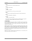
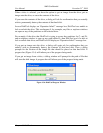
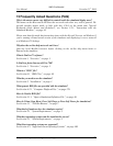
4. View the Diagnostic Port Output in the Main Window, as shown in Figure 14-2.
Figure 14-2: Diagnostics Display
The Diagnostic Display displays data written to three I/O address ranges, 0x80-0x83,
0x84-0x87, 0xE0-0xE3. Currently, the Diagnostic Display is implemented only for
Southbridge device. If the system configuration includes a Southbridge device, then the
Diagnostic Display will be displayed.
14.5 Logging PCI Configuration Cycles
Northbridge devices can be configured to produce PCI configuration-cycle log messages.
Complete the following steps to enable and capture of these log messages.
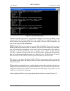
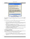
1. Open the Device Window from the Main Window Menu (“View→Show
Devices”). Double-click on the Northbridge device. This will bring up the device
Properties Window. Click on Logging Capabilities that will display the logging
options. Select Log PCI Configuration Cycle to and then click OK to accept the
configuration.
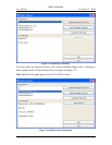
2. Select "View→Log Window" from the Main Window Menu. This will bring up a
Message Log dialog box similar to the one shown in Figure 14-3.