


Chapter 6 Control Modes of Operation|ASDA-AB Series
Revision January 2009 6-3
• Value B: Input pulse filter
B=0: 500Kpps
B=1: 200Kpps
B=2: 150Kpps
B=3: 80Kpps
This setting is used to suppress or reduce the
chatter caused by the noise, etc. However, if
the instant input pulse filter frequency is over
high, the frequency that exceeds the setting
value will be regarded as noise and filtered.
• Value C: Logic type
0=Positive Logic 1=Negative Logic
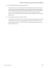
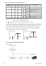
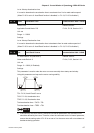
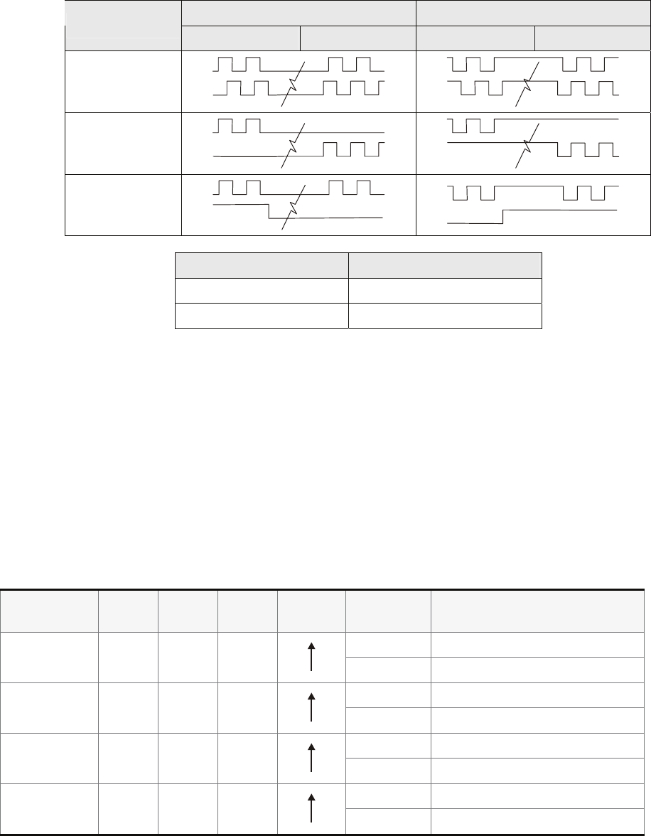
Pulse Type
Forward Reverse Forward Reverse
AB phase pulse
CW + CCW pulse
Pulse + Direction
Input pulse interface Max. input pulse frequency
Line driver 500kpps
Open collector 200kpps
• Other setting: Reversed
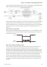
Position pulse can be input from these terminals, PULSE (41), /PULSE (43) and SIGN (37), /SIGN (36).
It can be an open-collector circuit or line driver circuit. For the detail wiring, please refer to 3.6.1.
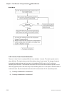
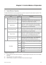
6.2.2 Command Source of Position (Pr) Control Mode
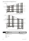
The command sources of Pr mode are P1-15, P1-16 to P1-29, P1-30 these eight built-in parameters.
According to parameter P1-33, users can select: a) Absolute or b) Incremental position control. Using
with external I/O signals (CN1, POS0 to POS 2 and CTRG) can select one of the eight built-in
parameters to be position command. Please refer to the table below:
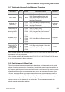
Position
Command
POS2 POS1 POS0 CTRG Parameters Description
P1-15 Rotation number (+/- 30000)
P1 0 0 0
P1-16 Pulses (+/- max cnt)
P1-17 Rotation number (+/- 30000)
P2 0 0 1
P1-18 Pulses (+/- max cnt)
P1-19 Rotation number (+/- 30000)
P3 0 1 0
P1-20 Pulses (+/- max cnt)
P1-21 Rotation number (+/- 30000)
P4 0 1 1
P1-22 Pulses (+/- max cnt)