


Chapter 8 MODBUS Communications|ASDA-AB Series
Revision January 2009 8-7
0306H
Digital Input
Communication
Function
Digital Input Contact Control:
Default: 0
Range: 0~FFFF (hexadecimal number)
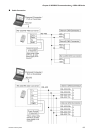
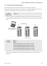
The setting of this parameter determines how the Digital Inputs (DI) accept commands and signals.
Input commands or signals through the DI can be either from an external source, through the CN 1
interface connector, or via communication, (RS-232, RS-485, RS-422). If the Digital Input Contact
Control parameter for the DI 1 ~ 8 is set to "0", command is external, and via CN1; if it is set to "1"
(decimal number) the DI signal is via communication. Each of the eight Digital Inputs are accessed
individually and can be set independently of each other. They can be programmed either via the drive's
keypad or via communication and computer UI. If they are programmed via the keypad a hexadecimal
number is entered; if programmed via communication or UI a decimal or hexadecimal number can be
used. In both methods of programming, a single number is used for all eight Digital Inputs. The following
example shows how each DI is addressed and converted to a single decimal or hexadecimal number.
The eight Digital Inputs are noted from the right, DI 1 to left, DI 8 with their desired input command or
signal method, 0 or 1. Once all eight Digital Inputs have been noted this binary number is converted to a
decimal or hexadecimal number and entered into P3-06.
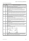
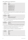
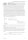
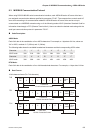
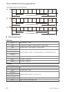
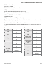
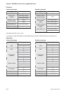
Bit 8 7 6 5 4 3 2 1
Decimal value 128 64 32 16 8 4 2 1
Input DI8 DI7 DI6 DI5 DI4 DI3 DI2 DI1
State 1 1 0 1 1 0 0 0 = D8 Hex
(Keypad, Communication or UI)
(External CN1
Communication)
or = 216 Dec (Communication or UI only)
Please see Chapter 4.4.5 DI Signal Display Diagnosis Operation for display layout of the Digital Signal
selection.
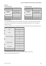
The Digital Input Control Contact parameter, P3-06 also works in conjunction with the Multi Function
Digital Input parameter P4-07 which has several functions.
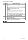
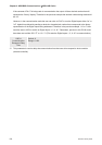
The contents of P4-07 is "read only" via the drive keypad and will display the state on or off ("blank" or
"|") of the eight Digital Inputs which have been set in accordance to P3-06. For Example; if P3-06 has
been set to 0 (All DI is external and via the CN 1 interface) and the P4-07 display is indicating the
following:
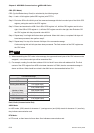
_ | | | _ _ _ | (for the manual this picture should be similar to the one shown on page 4-8
(Ch 4.4.5))
The Digital Inputs 1, 5, 6, & 7 are "on" (high) and Digital Inputs 2, 3, 4, & 8 are "off" (low).