


Chapter 3 Connections and Wiring|ASDA-AB Series
Revision January 2009 3-25
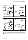
NOTE
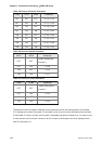
1) For Pin numbers of DI1~DI8 signals, please refer to section 3.3.1.
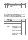
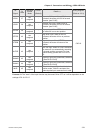
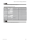
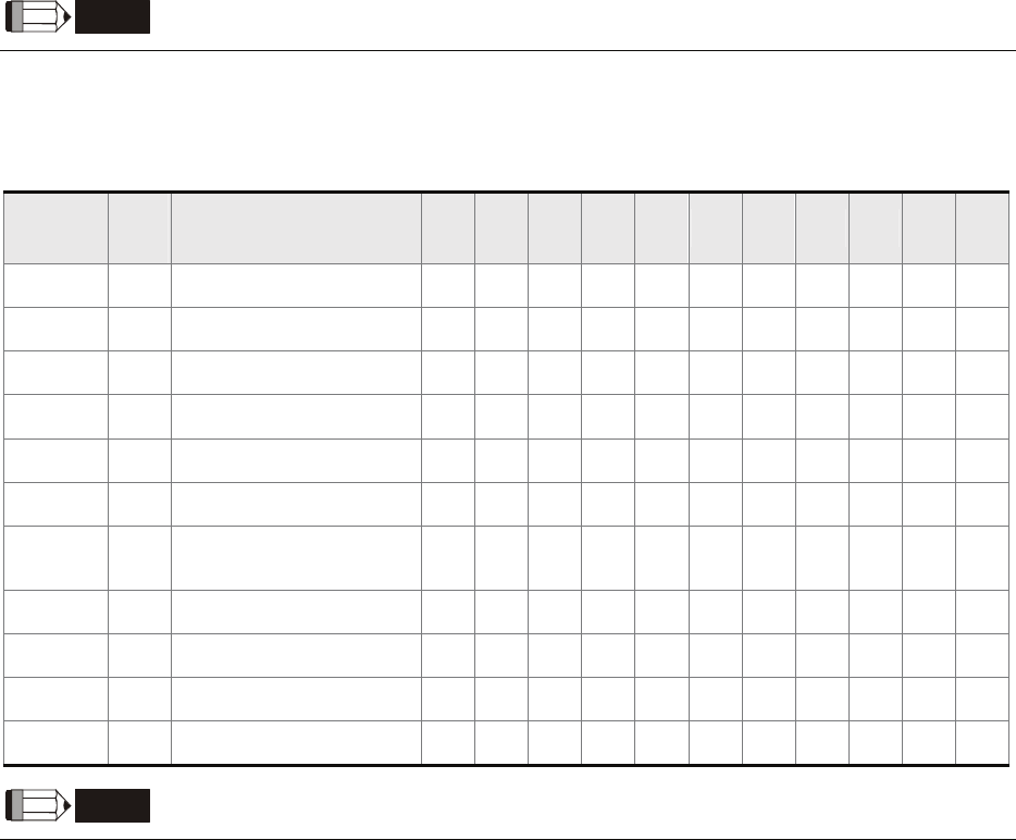
Table 3.H Default DO signals and Control modes
Signal
DO
Code
Function Pt Pr S T Sz Tz Pt-S Pt-T Pr-S Pr-T S-T
SRDY 01 Servo ready DO1 DO1 DO1 DO1 DO1 DO1 DO1 DO1 DO1 DO1 DO1
SON 02 Servo On
ZSPD 03 Zero speed DO2 DO2 DO2 DO2 DO2 DO2 DO2 DO2 DO2 DO2 DO2
TSPD 04 Speed reached DO3 DO3 DO3 DO3 DO3 DO3 DO3 DO3 DO3
TPOS 05 Positioning completed DO4 DO4 DO4 DO4 DO4 DO4 DO4
TQL 06 Reached torques limits
ALRM 07
Servo alarm output
(Servo fault)
DO5 DO5 DO5 DO5 DO5 DO5 DO5 DO5 DO5 DO5 DO5
BRKR 08 Electromagnetic brake DO4 DO4 DO4 DO4
HOME 09 Home completed DO3DO3
OLW 10 Output overload warning
WARN 11 Servo warning output
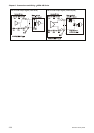
NOTE
1) For Pin numbers of DO1~DO5 signals, please refer to section 3.3.1.