


Chapter 5 Trial Run and Tuning Procedure|ASDA-AB Series
Revision January 2009 5-3
5.2 Applying Power to the Drive
The users please observe the following steps when applying power supply to the servo drive.
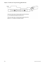
1. Please check and confirm the wiring connection between the drive and motor is correct.
1) Terminal U, V, W and FG (frame ground) must connect to Red, White, Black and Green cables
separately (U: Red, V: White, W: Black, FG: Green). If not connect to the specified cable and
terminal, then the drive cannot control motor. The motor grounding lead, FG must connect to
grounding terminal. For more information of cables, please refer to section 3.1.
2) Ensure to connect encoder cable to CN2 connector correctly. If the users only desire to execute
JOG operation, it is not necessary to make any connection to CN1 and CN3 connector. For more
information of the connection of CN2 connector, please refer to Section 3.1 and 3.4.
¾ Do not connect the AC input power (R, S, T (L1M, L2M)) to the (U, V, W) output terminals. This will damage
the AC servo drive.
2. Main circuit wiring
Connect power to the AC servo. For three-phase input power connection and single-phase input power
connection, please refer to Section 3.1.3.
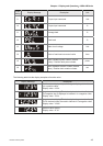
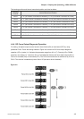
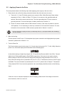
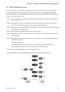
3. Turn the Power On
The Power includes control circuit power (L1, L2) and main circuit power (R, S, T (L1M, L2M)). When the
power is on, the normal display should be shown as the following figure:
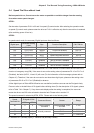
As the default settings of digital input signal, DI6, DI7 and DI8 are Reverse Inhibit Limit (CWL), Forward
Inhibit Limit (CCWL) and Emergency Stop (EMGS) respectively, if the users do not want to use the
default settings of DI6~DI8, the users can change their settings by using parameters P2-15 to P2-17
freely. When the setting value of parameters P2-15 to P2-17 is 0, it indicates the function of this DI signal
is disabled. For more information of parameters P2-15 to P2-17, please refer to Chapter 7 “Parameters”.
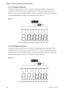
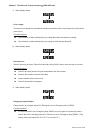
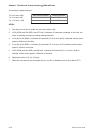
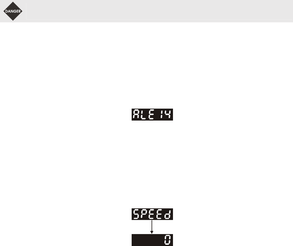
If the parameter P0-02 is set as motor speed (06), the normal display should be shown as the following
figure:
If there is no text or character displayed on the LED display, please check if the voltage of the control
circuit terminal (L1and L2) is over low.