


Chapter 6 Control Modes of Operation|ASDA-AB Series
6-42 Revision January 2009
P4 - 21
DOF2 Analog Monitor Output Drift Adjustment (CH2) Communication Addr.: 0415H
Default: Factory setting Related Section: N/A
Applicable Control Mode: P/S/T Section 6.4.4
Unit: mV
Range: -800~800
This parameter cannot be reset.
For example, when the users want to observe the analog voltage signal of channel 1, if the monitor
output setting range is 8V per 325Kpps, then it is needed to change the setting value of parameter P1-
04 (Analog Monitor Output Proportion 1) to 50 (=325Kpps/Max. input frequency). Other related
parameters setting include parameter P0-03 (A=3) and P1-03 (A=0~3, output polarity setting). In
general, when output voltage value of Ch1 is V1, the pulse command frequency is equal to (Max. input
frequency × V1/8) × P1-04/100.
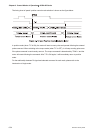
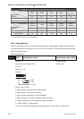
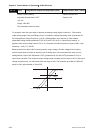
Because there is an offset value of analog monitor output voltage, the zero voltage level of analog
monitor output does not match to the zero point of setting value. We recommend the users can use
Analog Monitor Output Drift Adjustment, DOF1 (parameter P4-20) and DOF2 (parameter P4-21) to
improve this condition. The maximum output voltage range of analog monitor output is ±8V. If the output
voltage exceed its limit, it is still limited within the range of ±8V. The revolution provided by ASDA-AB
series is 10bit, approximated to 13mv/LSB.
8V
DOF
-8V