


Chapter 12 Application Examples |ASDA-AB Series
Revision January 2009 12-11
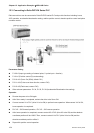
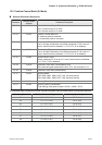
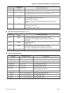
12.5 Position Control Mode (Pr Mode)
Relevant Parameters Description
Parameter
Communication
Address
Parameter Description
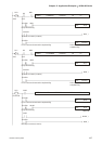
P1-01 0101H Control Mode and Output Direction
001: Forward torque in Pr mode
101: Reverse torque in Pr mode
P1-33 0121H Position Control Mode (Pr)
0: Absolute position command
1: Incremental position command
P1-34 0122H Acceleration Time
1st to 3rd step Acceleration time (When parameter P1-36 is set to 0,
accel / decel function is disabled, i.e. P1-34, P1-35 is disabled)
P1-35 0123H Deceleration Time
1st to 3rd step Deceleration time (When parameter P1-36 is set to 0,
accel / decel function is disabled, i.e. P1-34, P1-35 is disabled)
P1-36 0124H Accel /Decel S-curve
When parameter P1-36 is set to 0, accel / decel function is disabled,
i.e. P1-34, P1-35 is disabled.
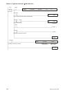
P1-44 012CH Electronic Gear Ratio (1st Numerator) (N1)
If the electronic gear deceleration ratio is 1/75, set numerator to 75
P1-45 012DH Electronic Gear Ratio (Denominator)
P1-47 012FH Homing Mode
202: When (MD1, MD0)=(OFF, ON), Forward Homing
203: When (MD1, MD0)=(OFF, ON), Reverse Homing
P1-50 0132H Homing Offset Rotation Number
P1-51 0133H Homing Offset Pulse Number
Total homing offset pulse number =P1-50 x 10000 + P1-51
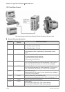
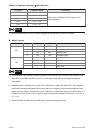
The following table indicates the position command registers and the corresponding moving speed registers.
Positioning Point Position Command Register Moving Speed Register
P1 ( P1-15, P1-16 ) P2-36 (V1)
P2 ( P1-17, P1-18 ) P2-37 (V2)
P3 ( P1-19, P1-20 ) P2-38 (V3)
P4 ( P1-21, P1-22 ) P2-39 (V4)
P5 ( P1-23, P1-24 ) P2-40 (V5)
P6 ( P1-25, P1-26 ) P2-41 (V6)
P7 ( P1-27, P1-28 ) P2-42 (V7)
P8 ( P1-29, P1-30 ) P2-43 (V8)