


Chapter 7 Servo Parameters|ASDA-AB Series
7-22
Revision January 2009
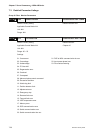
P0 - 03 MON Analog Monitor Output Communication Addr.: 0003H
Default: 01 Related Section:
Applicable Control Mode: ALL Section 4.3.5
Unit: N/A
Range: 00 ~ 55
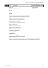
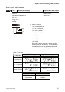
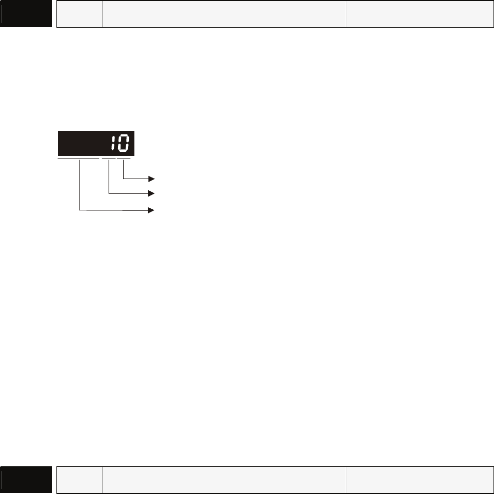
Settings:
not used
A
: CH1
B: CH2
AB: (A: CH1; B: CH2)
0: Motor speed (+/-8V / maximum motor speed)
1: Motor torque (+/-8V / maximum torque)
2: Pulse command frequency (+8Volts / 650Kpps)
3: Speed command (+/-8Volts / maximum speed command)
4: Torque command (+/-8Volts / maximum torque command)
5: V_BUS voltage (+/-8Volts / 450V)
Note: For the setting of analog output voltage proportion, refer to the P1-04 and P1-05.
Example:
P0-03 = 01(CH1 is speed analog output)
Motor speed = (Max. motor speed × V1/8) × P1-04/100, when the output voltage value of CH1 is
V1.
P0 - 04 CM1 Status Monitor 1 Communication Addr.: 0004H
Default: 0 Related Section:
Applicable Control Mode: ALL Section 4.3.5
Unit: N/A
Range: 0 ~ 16
Settings:
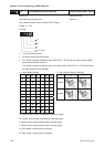
Select the desired drive status through communication setting or the keypad (please refer to P0-
02). The drive status can be read from the communication address of this parameter via
communication port.
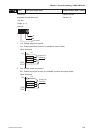
For example:
Set P0-04 to 1 and then all consequent reads of P0-04 will return the motor feedback rotation
number in revolution.