


Chapter 3 Connections and Wiring|ASDA-AB Series
Revision January 2009 3-19
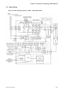
NOTE
1) PINS 3 & 2 can either be TSPD or HOME dependent upon control mode selected.
2) PINS 1 & 26 are different depending on control mode either BRKR or TPOS.
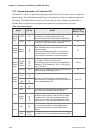
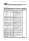
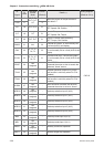
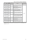
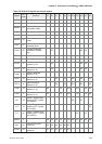
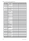
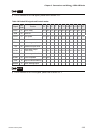
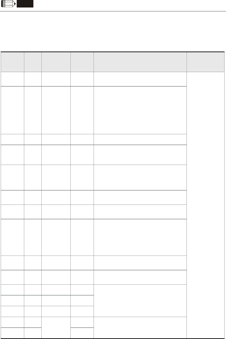
Table 3.C DI Signals
DI
Signal
DI
Code
Assigned
Control
Mode
Pin No.
(Default)
Details
(*2)
Wiring Diagram
(Refer to 3-3-3)
SON 01 ALL 9
Servo On. Switch servo to "Servo Ready".
Check parameter P2-51.
ARST 02 ALL 33
A number of Faults (Alarms) can be
cleared by activating ARST. Please see
table 10-3 for applicable faults that can be
cleared with the ARST command.
However, please investigate Fault or
Alarm if it does not clear or the fault
description warrants closer inspection of
the drive system.
GAINUP 03 ALL - Gain switching
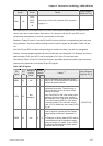
CCLR 04 Pt 10
When CCLR is activated the setting is
parameter P2-50 Pulse Clear Mode is
executed.
ZCLAMP 05 ALL -
When this signal is On and the motor
speed value is lower than the setting value
of P1-38, it is used to lock the motor in the
instant position while ZCLAMP is On.
CMDINV 06 Pr, T, S -
When this signal is On, the motor is in
reverse rotation.
HOLD 07
Not
assigned
Internal position control command pause
CTRG 08
Pr,
Pr-S, Pr-T
10
When the drive is in Pr mode and CTRG is
activated, the drive will command the
motor to move the stored position which
correspond the POS 0, POS 1, POS 2
settings. Activation is triggered on the
rising edge of the pulse.
TRQLM 09 S, Sz 10
ON indicates the torque limit command is
valid.
SPDLM 10 T, Tz 10
ON indicates the speed limit command is
valid.
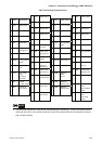
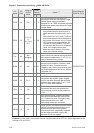
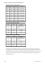
POS0 11 Pr 34
POS1 12 Pr-S, Pr-T 8
POS2 13 - -
When the Pr Control Mode is selected the
8 stored positions are programmed via a
combination of the POS 0, POS 1, and
POS 2 commands. See table 3.D.
SPD0 14 34
SPD1 15
S, Sz, Pt-S,
Pr-S, S-T
8
Select the source of speed command:
See table 3.E.
C9/C10