


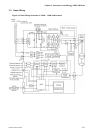
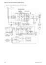
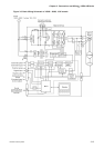
Chapter 3 Connections and Wiring|ASDA-AB Series
Revision January 2009 3-15
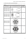
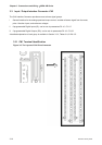
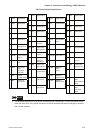
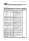
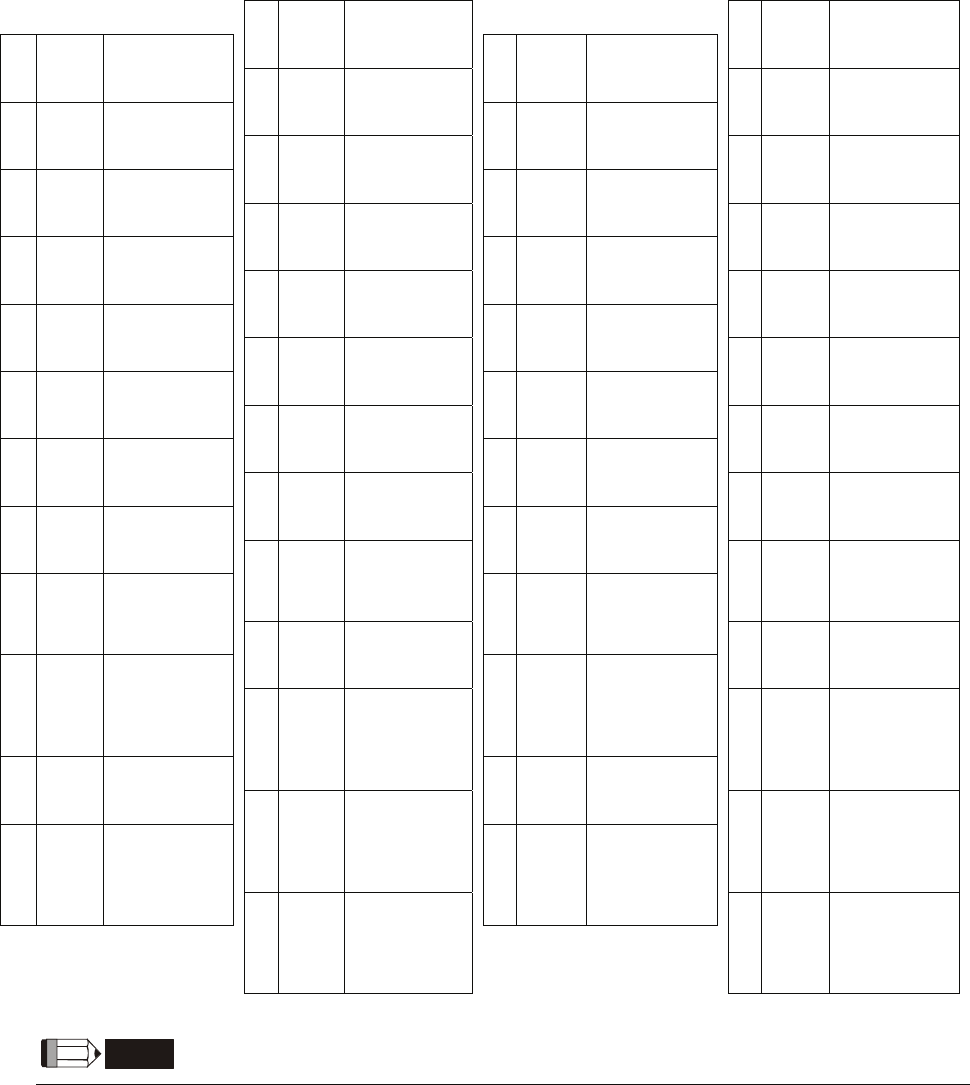
CN1 Terminal Signal Identification
1 DO4+ Digital output 26 DO4- Digital output
2 DO3- Digital output 27 DO5- Digital output
3 DO3+ Digital output 28 DO5+ Digital output
4 DO2- Digital output 29 NC No Connection
5 DO2+ Digital output 30 DI8- Digital input
6 DO1- Digital output 31 DI7- Digital input
7 DO1+ Digital output 32 DI6- Digital input
8 DI4- Digital input 33 DI5- Digital input
9 DI1- Digital input 34 DI3- Digital input
10 DI2- Digital input 35
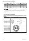
11 COM+
PULL
HI
Pulse applied
power
36 SIGN
12 GND
Power input
(12~24V)
37 /SIGN
Position sign
(+)
Analog input
signal ground
13 GND
Position sign (-
)
38 NC No Connection
14 NC No Connection
Analog input
signal ground
39 NC No Connection
15 MON2 40 NC No Connection
16 MON1
Analog monitor
output 2
41 /PULSE Pulse input (-)
Analog monitor
output 1
17 VDD 42 V_REF
18 T_REF
+24V power
output (for
external I/O)
43 PULSE Pulse input (+)
Analog speed
input (+)
Analog torque
Input
19 GND 44 GND
20 VCC
Analog input
signal ground
45 COM-
Analog input
signal ground
+12V power
output
(for analog
command)
21 OA
VDD(24V)
power
ground
46 NC No Connection
22 /OA
Encoder
A pulse output
47 COM-
Encoder
/A pulse output
23 /OB
VDD(24V)
power ground
48 OCZ
24 /OZ
Encoder /B
pulse output
49 COM- VDD(24V)
power ground
Encoder Z
pulse
Open-collector
output
Encoder /Z
pulse output
25 OB 50 OZ
Encoder B
pulse output
Encoder Z
pulse
Line-driver
output
NOTE
1) The terminals marked "NC" must be left unconnected (No Connection). The NC terminals are used
within the servo drive. Any outside connection to the NC terminals will result in damage to the drive
and void the warranty!