


Chapter 6 Control Modes of Operation|ASDA-AB Series
6-24 Revision January 2009
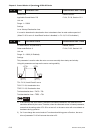
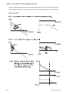
users usually use time domain method with the analog DI/DO terminal provided by the servo drive to
adjust what is called as PI (Proportional and Integral) type controller. As for the performance of torque
shaft load, input command tracking and torque shaft load have the same responsiveness when using
frequency domain method and time domain method. The users can reduce the responsiveness of input
command tracking by using input command low-pass filter.
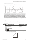
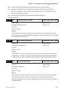
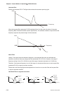
Auto Mode (Continuous adjustment))
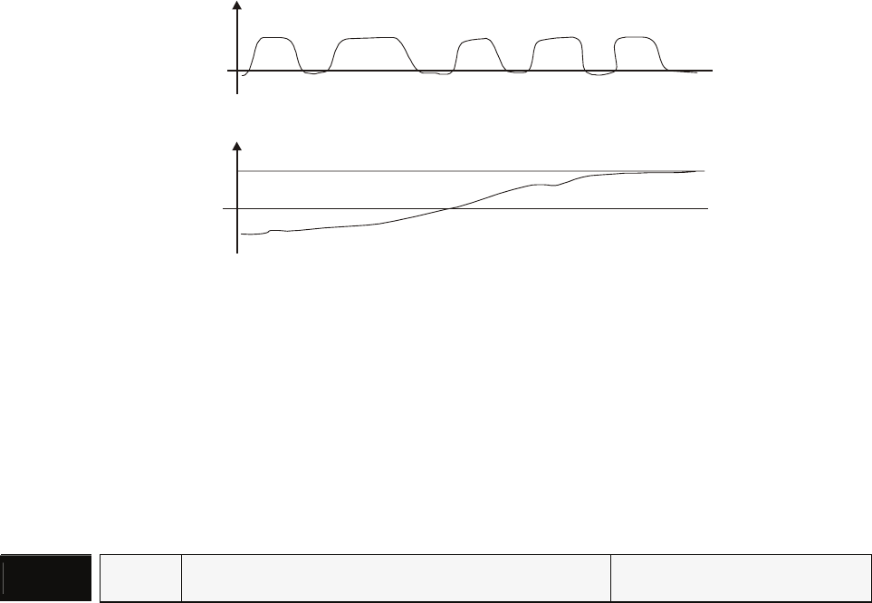
This Auto Mode provides continuous adjustment of loop gains according to measured inertia
automatically. It is suitable when the load inertia is fixed or the load inertia change is small and is not
suitable for wide range of load inertia change. The period of adjustment time is different depending on
the acceleration and deceleration of servo motor. To change the stiffness and responsiveness, please
use parameter P2-31.
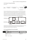
W
J
Motor Speed
Inertia Measurement
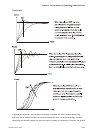
6.3.7 Resonance Suppression
The resonance of mechanical system may occur due to excessive system stiffness or frequency
response. However, this kind of resonance condition can be improved, suppressed, even can be
eliminated by using low-pass filter (parameter P2-25) and notch filter (parameter P2-23, P2-24) without
changing control parameter.
Relevant parameters:
P2 - 23
NCF Notch Filter (Resonance Suppression) Communication Addr.: 0217H
Default: 1000 Related Section:
Applicable Control Mode: P/S/T Section 6.3.7
Unit: Hz
Range: 50 ~ 1000
Settings:
This parameter is used to set resonance frequency of mechanical system. It can be used to
suppress the resonance of mechanical system. If P2-24 is set to 0, this parameter is disabled.