


Chapter 12 Application Examples|ASDA-AB Series
12-26 Revision January 2009
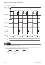
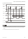
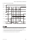
When the setting value of the time listed below is set to zero(0), the relative position will be ignored.
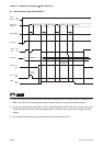
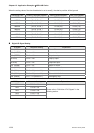
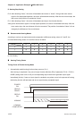
Positioning Point Position Command Register Moving Speed Register Dwell Time Register
INDEX1 ( P1-15, P1-16 ) P2-36 (V1) P2-52 (T1)
INDEX2 ( P1-17, P1-18 ) P2-37 (V2) P2-53 (T2)
INDEX3 ( P1-19, P1-20 ) P2-38 (V3) P2-54 (T3)
INDEX4 ( P1-21, P1-22 ) P2-39 (V4) P2-55 (T4)
INDEX5 ( P1-23, P1-24 ) P2-40 (V5) P2-56 (T5)
INDEX6 ( P1-25, P1-26 ) P2-41 (V6) P2-57 (T6)
INDEX7 ( P1-27, P1-28 ) P2-42 (V7) P2-58 (T7)
INDEX8 ( P1-29, P1-30 ) P2-43 (V8) P2-59 (T8)
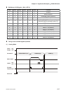
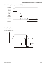
Digital I/O Signal Setting
DI Signal Parameter Setting Explanation
DI1 (SON) P2-10 = 101 Servo ON
DI2 (AUTOR) P2-11 = 142 Auto run input
DI3 (STEPD) P2-12 = 140 Step down input
(STEPU) P2-12 = 139
Step up input
(STEPB) P2-12 = 141
Step back input.
DI4 (SHOM) P2-13 = 127 Move to “Home”
DI5 (ORGP) P2-14 = 124 Reference “Home” sensor
DI6 (CWL) P2-15 = 22 (contact “b”)
Reverse Inhibit limit
DI7 (CCWL) P2-16 = 23 (contact “b”) Forward Inhibit limit
DI8 (EMGS) P2-17 = 21 (contact “b”) Emergency stop
DO Signal Parameter Setting Explanation
DO1 P2-18 = 101
DO2 P2-19 = 103
DO3 P2-20 = 109
DO4 P2-21 = 105
DO5 P2-22 = 107
Please refer to “Definition of DO Signals” in the
following section.