


Chapter 6 Control Modes of Operation|ASDA-AB Series
6-10 Revision January 2009
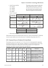
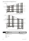
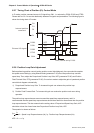
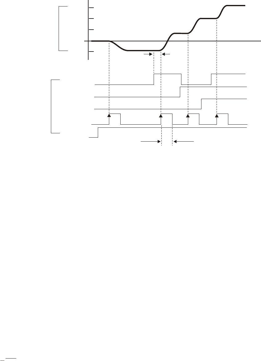
6.2.7 Timing Chart of Position (Pr) Control Mode
In Pr mode, position command source is DI signal from CN1, i.e. selected by POS0~POS2 and CTRG.
Please refer to 6-2-2 to see the relationship between DI signals and parameters. The following figure is
shown the timing chart of Pr mode:
P8
P3
P2
P1
POS0
POS1
CTRG
SON
External I/O signal
OFF
ON
OFF
ON
ON
OFF
ON
>2ms, can be set b
y
P2-09
POS2
ON
OFF
Internal position
command
1ms
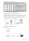
6.2.8 Position Loop Gain Adjustment
Before performing position control (setting position control block diagram), the users should complete
the speed control setting by using Manual mode (parameter P-32) since the position loop contains
speed loop. Then, adjust the Proportional Position Loop Gain, KPP (parameter P2-00) and Position
Feed Forward Gain, PFG (parameter P2-02). Or use Auto mode to adjust the gain of speed and position
control block diagram automatically.
1) Proportional Position Loop Gain: To increase this gain can enhance the position loop
responsiveness.
2) Position Feed Forward Gain: To increase this gain can reduce the position track error during
operation.
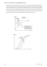
The position loop responsiveness cannot exceed the speed loop responsiveness, and it is
recommended that the speed loop responsiveness should be at least four times faster than the position
loop responsiveness. This also means that the setting value of Proportional Speed Loop Gain, KVP
should be at least four times faster than Proportional Position Loop Gain, KPP.
The equation is shown as follows:
fp<
fv
4
, fv : Speed Loop Responsiveness (Hz), fp : Position Loop Responsiveness (Hz)
KPP = 2 × π × fp.