


Chapter 7 Servo Parameters|ASDA-AB Series
7-8
Revision January 2009
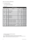
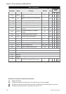
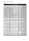
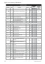
Group 4: P4-xx
Diagnosis Parameters
Control
Mode
Parameter Name Function Default Unit
Pt Pr S T
P4-00★
ASH1 Fault Record (N) 0 N/A
{ { { {
P4-01★
ASH2 Fault Record (N-1) 0 N/A
{ { { {
P4-02★
ASH3 Fault Record (N-2) 0 N/A
{ { { {
P4-03★
ASH4 Fault Record (N-3) 0 N/A
{ { { {
P4-04★
ASH5 Fault Record (N-4) 0 N/A
{ { { {
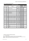
P4-05 JOG JOG Operation 20 r/min
{ { { {
P4-06▲■
FOT Force Output Control 0 N/A
{ { { {
P4-07■
ITST Input Status or Force Input Control N/A N/A
{ { { {
P4-08 PKEY Digital Keypad Input of Servo Drive N/A N/A
{ { { {
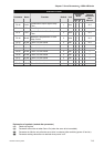
P4-09★
MOT Output Status Display
N/A
N/A
{ { { {
P4-10▲
CEN Adjustment Function 0 N/A
{ { { {
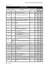
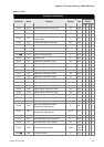
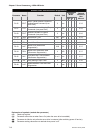
P4-11 SOF1 Analog Speed Input Drift Adjustment 1
Factory
setting
N/A
{ { { {
P4-12 SOF2 Analog Speed Input Drift Adjustment 2
Factory
setting
N/A
{ { { {
P4-13 TOF1 Analog Torque Drift Adjustment 1
Factory
setting
N/A
{ { { {
P4-14 TOF2 Analog Torque Drift Adjustment 2
Factory
setting
N/A
{ { { {
P4-15 COF1
Current Detector Drift Adjustment (V1
phase)
Factory
setting
N/A
{ { { {
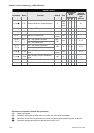
P4-16 COF2
Current Detector Drift Adjustment (V2
phase)
Factory
setting
N/A
{ { { {
P4-17 COF3
Current Detector Drift Adjustment (W1
phase)
Factory
setting
N/A
{ { { {
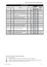
P4-18 COF4
Current Detector Drift Adjustment (W2
phase)
Factory
setting
N/A
{ { { {
P4-19 TIGB IGBT NTC Calibration
Factory
setting
N/A
{ { { {
P4-20 DOF1
Analog Monitor Output Drift Adjustment
(CH1)
0 mV
{ { { {
P4-21 DOF2
Analog Monitor Output Drift Adjustment
(CH2)
0 mV
{ { { {
P4-22 SAO Analog Speed Input Offset 0 mV
{
P4-23 TAO Analog Torque Input Offset 0 mV
{