


Chapter 6 Control Modes of Operation|ASDA-AB Series
Revision January 2009 6-41
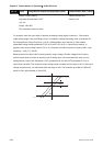
Example: P0-03 = 01(CH1 is speed analog output)
Motor rotation speed = (Max. rotation speed × V1/8) × P1-04/100, when the output voltage value
of CH1 is V1.
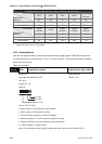
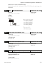
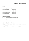
P1 - 03
AOUT Pulse Output Polarity Setting Communication Addr.: 0103H
Default: 0 Related Section:
Applicable Control Mode: P/S/T Section 3.3.3
Unit: N/A
Range: 0 ~ 1
Settings:
not used
A
B
Monitor analog output polarity
• A=0: MON1(+), MON2(+)
• A=1: MON1(+), MON2(-)
• A=2: MON1(-), MON2(+)
• A=3: MON1(-), MON2(-)
Pulse output polarity
• B=0: Forward output
• B=1: Reverse output
P1 - 04
Analog Monitor Output Proportion 1 (CH1) Communication Addr.: 0104H
Default: 100 Related Section:
Applicable Control Mode: P/S/T Section 6.4.4
Unit: % (full scale)
Range: 0 ~ 100
P1 - 05
Analog Monitor Output Proportion 2 (CH2) Communication Addr.: 0105H
Default: 100 Related Section:
Applicable Control Mode: P/S/T Section 6.4.4
Unit: % (full scale)
Range: 0~100
P4 - 20
DOF1 Analog Monitor Output Drift Adjustment (CH1) Communication Addr.: 0414H
Default: Factory setting Related Section:
Applicable Control Mode: P/S/T Section 6.4.4
Unit: mV
Range: -800~800
This parameter cannot be reset.