


Chapter 7 Servo Parameters|ASDA-AB Series
7-16
Revision January 2009
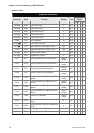
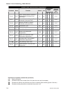
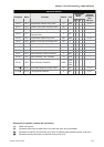
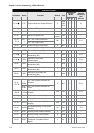
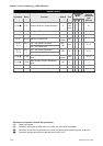
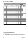
Digital I/O and relative input output setting
Digital I/O
Control
Mode
Parameter Name Function Default Unit
Pt Pr S T
Related
Section of
User
Manual
P2-09 DRT Bounce Filter 2 2ms
{ { { {
P2-10 DI1 Digital Input Terminal 1 (DI1) 101 N/A
{ { { {
P2-11 DI2 Digital Input Terminal 2 (DI2) 104 N/A
{ { { {
P2-12 DI3 Digital Input Terminal 3 (DI3) 116 N/A
{ { { {
P2-13 DI4 Digital Input Terminal 4 (DI4) 117 N/A
{ { { {
P2-14 DI5 Digital Input Terminal 5 (DI5) 102 N/A
{ { { {
P2-15 DI6 Digital Input Terminal 6 (DI6) 22 N/A
{ { { {
P2-16 DI7 Digital Input Terminal 7 (DI7) 23 N/A
{ { { {
Table 7.A
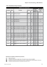
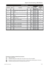
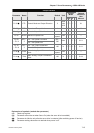
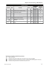
P2-17 DI8 Digital Input Terminal 8 (DI8) 21 N/A
{ { { {
P2-18 DO1 Digital Output Terminal 1 (DO1) 101 N/A
{ { { {
P2-19 DO2 Digital Output Terminal 2 (DO2) 103 N/A
{ { { {
P2-20 DO3 Digital Output Terminal 3 (DO3) 109 N/A
{ { { {
P2-21 DO4 Digital Output Terminal 4 (DO4) 105 N/A
{ { { {
P2-22 DO5 Digital Output Terminal 5 (DO5) 7 N/A
{ { { {
Table 7.B
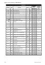
P1-38 ZSPD Zero Speed Range Setting 10 r/min
{ { { {
---
P1-39 SSPD Target Motor Speed 3000 r/min
{ { { {
---
P1-42 MBT1
On Delay Time of Electromagnetic
Brake
0 ms
{ { { {
6.5.5
P1-43 MBT2
OFF Delay Time of Electromagnetic
Brake
0 ms
{ { { {
6.5.5
P1-54 PER Positioning Completed Width 100 pulse
{ {
---
P1-56 OVW Output Overload Warning Level 120 %
{ { { {
---
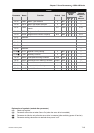
Explanation of symbols (marked after parameter)
(★) Read-only register.
(▲) Parameter cannot be set when Servo On (when the servo drive is enabled).
(●) Parameter is effective only after the servo drive is restarted (after switching power off and on).
(■) Parameter setting values are not retained when power is off.