


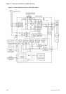
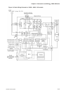

Chapter 3 Connections and Wiring|ASDA-AB Series
3-20 Revision January 2009
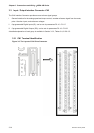
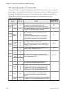
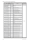
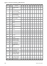
DI
Signal
DI
Code
Assigned
Control
Mode
Pin No.
(Default)
Details
(*2)
Wiring Diagram
(Refer to 3-3-3)
TCM0 16 34
TCM1 17
Pt, T, Tz,
Pt-T, Pr-T,
S-T
8
Select the source of torque command:
See table 3.F.
S-P 18 Pt-S, Pr-S 31
Speed / Position mode switching
OFF: Speed, ON: Position
S-T 19 S-T 31
Speed / Torque mode switching
OFF: Speed, ON: Torque
T-P 20 Pt-T, Pr-T 31
Torque / Position mode switching
OFF: Torque, ON: Position
EMGS 21 ALL 30
It should be contact “b” and normally ON
or a fault (ALE13) will display.
CWL 22
Pt, Pr, S, T
Sz, Tz
32
Reverse inhibit limit. It should be contact
“b” and normally ON or a fault (ALE14) will
display.
CCWL 23
Pt, Pr, S, T
Sz, Tz
31
Forward inhibit limit. It should be contact
“b” and normally ON or a fault (ALE15) will
display.
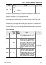
ORGP 24
Not
assigned
-
When ORGP is activated, the drive will
command the motor to start to search the
reference “Home” sensor.
TLLM 25
Not
assigned
-
Reverse operation torque limit (Torque
limit function is valid only when P1-02 is
enabled)
TRLM 26
Not
assigned
-
Forward operation torque limit (Torque
limit function is valid only when P1-02 is
enabled)
SHOM 27
Not
assigned
-
When SHOM is activated, the drive will
command the motor to move to “Home”.
INDEX0 28
Not
assigned
- Feed step selection input 0 (bit 0)
INDEX1 29
Not
assigned
- Feed step selection input 1 (bit 1)
INDEX2 30
Not
assigned
- Feed step selection input 2 (bit 2)
INDEX3 31
Not
assigned
- Feed step selection input 3 (bit 3)
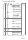
INDEX4 32
Not
assigned
- Feed step selection input 4 (bit 4)
MD0 33
Not
assigned
- Feed step mode input 0 (bit 0)
MD1 34
Not
assigned
- Feed step mode input 1 (bit 1)
MDP0 35
Not
assigned
- Manually continuous operation
MDP1 36
Not
assigned
- Manually single step operation
C9/C10