


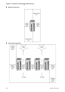
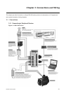
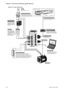

Chapter 3 Connections and Wiring|ASDA-AB Series
Revision January 2009 3-3
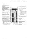
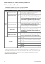
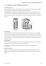
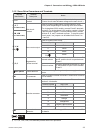
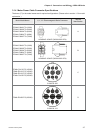
3.1.2 Servo Drive Connectors and Terminals
Terminal
Identification
Terminal
Description
Notes
L1, L2
Control circuit
terminal
Used to connect single-phase AC control circuit power.
(Control circuit uses the same voltage as the main circuit.)
R, S, T
(for 220V models)
L1M, L2M
(for 110V models)
Main circuit
terminal
Used to connect single-phase or three-phase AC main
circuit power depending on connecting servo drive model.
For single-phase 220V models, connect R and S terminals
to power. For single-phase 110V models, connect L1M and
L2M terminals to power. For three-phase models, connect
all three R, S, and T terminals to power. To provide control
circuit power, two jumpers can be added from R and S to
L1 and L2.
Used to connect servo motor
Terminal Symbol Wire Color
U Red
V White
W Black
U, V, W
FG (
)
Servo motor output
FG(
)
Green
Internal resistor
Ensure the circuit is closed between P
and D, and the circuit is open between
P and C.
P, D, C
Regenerative
resistor terminal
External resistor
Connect regenerative resistor to P and
C, and ensure an open circuit between
P and D.
two places
Ground terminal
Used to connect grounding wire of power supply and servo
motor.
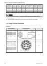
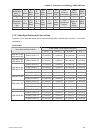
CN1
I/O connector
Used to connect external controllers. Please refer to section
3.3 for details.
Used to connect encoder of servo motor. Please refer to
section 3.4 for details.
Terminal Symbol Wire Color
A Black
/A Black/Red
B White
/B White/Red
Z Orange
/Z Orange/Red
+5V Brown & Brown/White
CN2
Encoder connector
GND Blue & Blue/White
CN3
Communication
connector
Used to connect PC or keypad. Please refer to section 3.5
for details.
NOTE
1) U, V ,W , CN1, CN2, CN3 terminals provide short circuit protection.