


Chapter 6 Control Modes of Operation|ASDA-AB Series
Revision January 2009 6-37
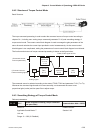
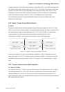
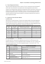
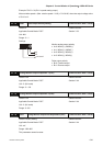
External Regenerative Resistor
When using external regenerative resistor, connect it to P and C, and make sure the circuit between P
and D is open. We recommend the users should use the external regenerative resistor that the
resistance value following the above table (Built-in Regenerative Resistor Specifications). We ignore the
dissipative power of IGBT (Insulated Gate Bipolar Transistor) in order to let the users easily calculate
the capacity of regenerative resistor. In the following sections, we will describe Regenerative Power
Calculation Method and Simple Calculation Method for calculating the regenerative power capacity of
external regenerative resistors.
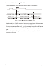
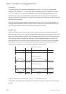
Regenerative Power Calculation Method
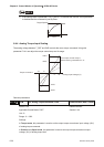
(1) Without Load
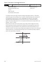
When there is no external load torque, if the servo motor repeats operation, the returned regenerative
power generated when braking will transmitted into the capacitance of DC bus. After the capacitance
voltage exceeds some high value, regenerative resistor can dissipate the remained regenerative power.
Use the table and procedure described below to calculate the regenerative power.
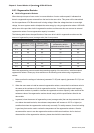
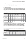
Servo Drive
(kW)
Rotor Inertia
J (kg. m
2
)
Regenerative power from empty load
3000r/min to stop Eo (joule)
Max. regenerative power
of capacitance Ec(joule)
0.1 0.03E-4 0.15 3
0.2 0.18E-4 0.89 4
0.4 0.34E-4 1.68 8
0.75 1.08E-4 5.34 14
1.0 2.60E-4 12.86 18
1.5 3.60E-4 17.80 18
2.0 4.70E-4 23.24 21
Eo = J x wr
2
/182 (joule) , Wr : r/min
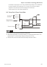
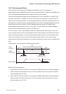
If the load inertia is N × motor inertia, the regenerative power will be (N+1) x E0 when servo motor
brakes from 3000r/min to 0. Then, the regenerative resistor can dissipate: (N+1) x E0 - Ec (joule). If the
time of repeat operation cycle is T sec, then the regenerative power = 2 x ((N+1) x E0 - Ec) / T. The
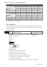
calculating procedure is as follows:
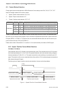
Step Procedure Equation and Setting Method
1
Set the capacity of regenerative
resistor to the maximum
Change the value of P1-53 to maximum
2 Set the operation cycle T Input by the users
3 Set motor speed wr Input by the users or read via P0-02 Drive State Display
4 Set load/motor inertia ratio N Input by the users or read via P0-02 Drive State Display
5
Calculate the max. regenerative
power Eo
Eo = J x wr
2
/182
6
Set the regenerative power Ec that
can be absorbed
Refer to the table above
7
Calculate the required
regenerative power capacity
2 x (N+1) x Eo-Ec)/ T