


Chapter 3 Connections and Wiring|ASDA-AB Series
3-16 Revision January 2009
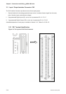
3.3.2 Signals Explanation of Connector CN1
The Tables 3.A, 3.B, & 3.C detail the three groups of signals of the CN1 interface. Table 3.A details the
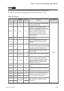
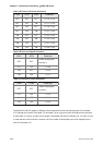
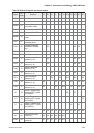
general signals. Table 3.B details the Digital Output (DO) signals and Table 3.C details the Digital Input
(DI) signals. The General Signals are set by the factory and can not be changed, reprogrammed or
adjusted. Both the Digital Input and Digital Output signals can be programmed by the users.
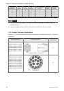
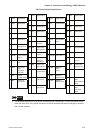
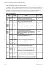
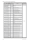
Table 3.A General Signals
Signal Pin No Details
Wiring Diagram
(Refer to 3-3-3)
V_REF 42
Motor speed command: -10V to +10V, corresponds
to the maximum speed programmed P1-55
Maximum Speed Limit (Factory default 3000 RPM).
C1
Analog
Signal
Input
T_REF 18
Motor torque command: -10V to +10V, corresponds
to -100% to +100% rated torque command.
C1
Analog
Monitor
Output
MON1
MON2
16
15
The MON1 and MON2 can be assigned drive and
motor parameters that can be monitored via an
analogue voltage.
Please reference parameter P0-03 for monitoring
commands and P1-04 / P1-05 for scaling factors.
Output voltage is reference to the power ground.
C2
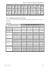
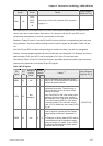
PULSE
/PULSE
SIGN
/SIGN
41
43
37
36
The drive can accept two different types of pulse
inputs: Open Collector and Line Driver.
Three different pulse commands can be selected via
parameter P1-00. Quadrature , CW + CCW pulse &
Pulse / Direction.
C3/C4
Position
Pulse
Input
PULL HI 35
Should an Open Collector type of pulse be used this
terminal must be lulled high to pin 17.
C3
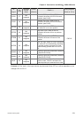
OA
/OA
21
22
OB
/OB
25
23
Position
Pulse
Output
OZ
/OZ
50
24
The motor encoder signals are available through
these terminals. The encoder output pulse count can
be set via parameter P1-46.
C11/C12
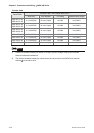
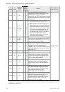
VDD 17
VDD is the +24V source voltage provided by the
drive. Maximum permissible current 500mA.
Power
COM+
COM-
11
45
47
49
COM+ is the common voltage rail of the Digital Input
and Digital Output signals. Connect VDD to COM+
for source mode. For external applied power sink
mode (+12V to +24V), the positive terminal should
be connected to COM+ and the negative to COM-.
-
VCC 20
VCC is a +12V power rail provided by the drive. It
can be used for the input on an analog speed or
torque command. Maximum permissible current
100mA.
Power
GND
12,13,
19,44
The polarity of VCC is with respect to Ground (GND).
-