


22 HCI disassembly/assembly ENWW
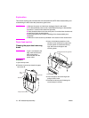
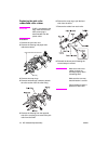
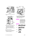
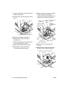
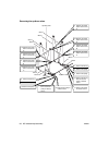
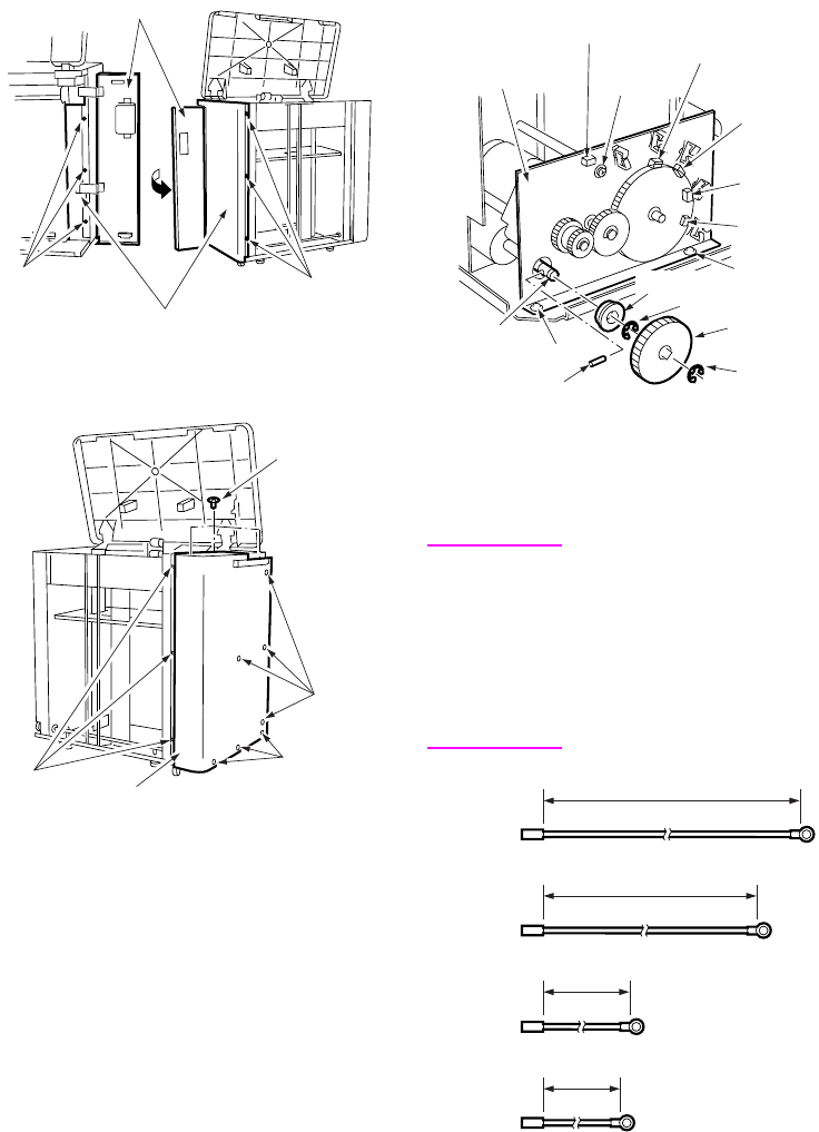
5 Remove twelve screws to detach the rear
cover.
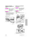
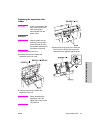
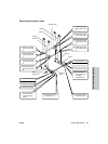
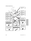
6 Remove the five relay connectors (CN749,
CN780, CN781, CN782, CN783) to
disconnect the wiring harness from the
up/down motor mounting assembly.
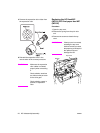
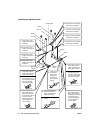
7 Remove the E-ring to detach the up/down
gear.
8 Pull the pin from the shaft.
9 Remove the E-ring to detach the bearing.
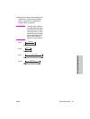
10 Remove three screws to detach the
up/down motor assembly.
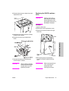
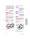
11 Replace the up/down wire following the
instructions in "Removing the up/down
wires" on page 23 and "Installing the
up/down wires" on page 24.
CAUTION Two sets of four up/down
wires with different length,
one set at the front and the
other at the back, are used.
Wires with the same length
can be used either at the
front or back if they are
used in the same location.
Jam access door
Screws
Right side cover
Screws
Screw
Screws
Screws
Screws
Rear cover
Up/down
motor mounting
assembly
Relay connector
(CN749)
Screw
Relay
connector
(CN780)
Relay
connector
(CN781)
Relay
connector
(CN782)
Relay
connector
(CN783)
Screw
Bearing
E-ring
Up/down
gear
E-ring
Pin
Screw
Shaft
1323.6mm
1250.3mm
769.3mm
661mm
Wire A
Wire B
Wire C
Wire D