


54 MFP unit explanation ENWW
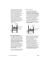
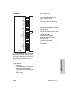
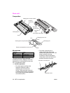
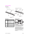
beams are radiated onto the drum surface.
Two beams are emitted per laser diode. Two
lines of image data is written per scan.
The write start reference position is detected
by the index sensor board. The ICB has an
E-RDH function to store digitized image
data. Various editing functions can be
performed based on this data.
1 Operation
a Image processing
The following processing is performed
by the ICB (image control board):
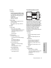
1 Automatic offset control (AOCl)
The IC on the A/D converter board
(ADB) automatically adjusts the
analog offset voltage of the CCD
sensor output so that it is at the lower
limit of the A/D converter level.
2 Automatic gain control (AGC)
During shading correction, the white
reference plate is read to adjust the
analog amplification factor of the CCD
sensor output so that the read level is
at the upper limit of the A/D converter
level.
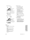
3 Shading correction
<Timing>
• When SW2 (sub power) is on
•At job start
4 Brightness/density conversion
5 AE processing
6 Text/dot pattern judgment
7 Filtering
8 Magnification change processing
9 Copy gamma correction
10 Skew correction
11 Error diffusion processing
12 Data compression/expansion
processing
13 Write density control
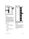
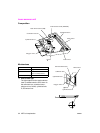
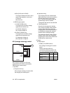
b Write
The image control board (ICB) sends
image data on a pixel basis to laser
driver board (LDB) according to the
control signals from the PRCB (printer
control board).
LDB causes the laser light to be emitted
for a period corresponding to the image
data. This laser light is radiated onto the
drum surface.
1 Maximum power control (MPC)
Image control board (ICB) informs
LDB (laser driver board) of the
maximum output value and sets that
value for the laser beam emission.
LDB store this value and maintain the
laser beam level using the APC (Auto
Power Control).
<MPC timing>
When SW2 (sub power switch) is
turned on
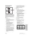
2 Automatic power control (APC)
After MPC is set, the ICB (image
control board) outputs an APC start
instruction to LDB (laser driver board)
at the following timing:
APC timing
LDB (laser driver board) automatically
monitor the laser drive current one
line at a time, and controls it so that
the light intensity remains the MPC
value.
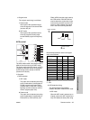
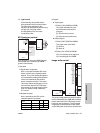
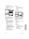
3 Write timing
a) Main scanning direction
Using INDEX signal (/IND) from
INDXSB (index sensor board), the
laser write reference position is
determined for each scan in the drum
rotation direction, and the image is
written onto the copy paper according
to the copy paper position detected
by PS70 (paper mis-centering).