


Connecting peripheral devices to the 201i server Standard 1.0
134 CallPilot
Overview
Introduction
This section describes installing the 201i server in the switch, connecting
peripheral devices, and starting the 201i server.
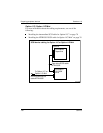
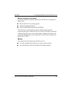
Connecting the 201i server to the network
The switch, ELAN, CLAN, and modem connections are established by
using the 201i server’s multi I/O cable.
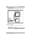
The switch connector is a 50-pin amphenol connector.
The RJ-45 CLAN and ELAN connectors support the following network
protocols:
ELAN: 10Base-T Ethernet
CLAN: 10/100Base-T Ethernet
The modem connector is a 9-pin male RS-232 connector. To connect this
cable to the modem, you also need a 25-pin male to 9-pin female shielded
serial cable (A0601464, supplied with the modem).
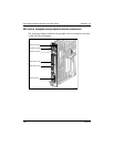
Connecting peripheral devices
MPC cards
Two MPC-8 cards are preinstalled at the factory. This section describes how
to install additional cards, if required.
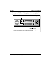
CD-ROM and tape drives
Before you connect CD-ROM and tape drives, ensure that you have set the
SCSI ID, termination, and DIP switches as described in Chapter 6,
“Preparing peripheral devices.”