


About the 201i server Standard 1.0
14 CallPilot
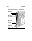
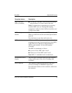
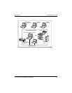
The following table describes each faceplate feature:
Faceplate feature Description
Mouse connector The mouse connector is a standard PS/2 connector and
is hot-pluggable.
Lock latches Lock latches at the top and bottom of the faceplate
secure the server to the backplane of the Meridian 1
switch or the backplane of the Succession CSE 1000
Media Gateway or Media Gateway Expansion.
Keyboard connector The keyboard connector is a standard PS/2 connector
and is hot-pluggable.
Infrared port For future use.
Monitor connector The monitor connector is a standard, high-density,
15-pin female connector.
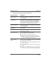
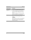
Power status LED The LED indicates two server states:
the completion of self-test diagnostics
when it is safe to remove the server from the
Meridian 1 switch or Succession CSE 1000 Media
Gateway or Media Gateway Expansion
MPC card status
LEDs
There is an LED for each MPC card slot. The following
list describes each LED status:
Off: The MPC card is not receiving power. It is safe
to remove the card.
On: The MPC card is in use. It is not safe to remove
the card.
Off, then on: The MPC card has been recognized by
the 201i server software and has been powered up.