


KIRK Repeater Installation 49
KIRK Wireless Server 600v3 Installation and Configuration Guide
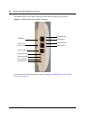
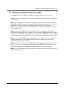
5.3.3 KIRK Repeater Appearance and Components
The KIRK Repeater mounting template includes two mounting holes that allow it to be affixed to
the wall. See
Figure 15 on page 51 and Figure 16 on page 51. The repeater connection panel
includes the following:
• Receive and transmit wire pair to connect to a KIRK Power Supply Repeater
Note: The KIRK Power Supply for the repeater is to be ordered separately (Part no. UK
version: 84642421, Part no. EU version: 84642420).
• LED that indicates whether or not the unit is functioning
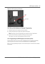
After connecting all ports, place the plastic cover on the connection panel to prevent dust and other
particles from entering the connection ports.
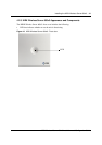
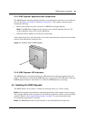
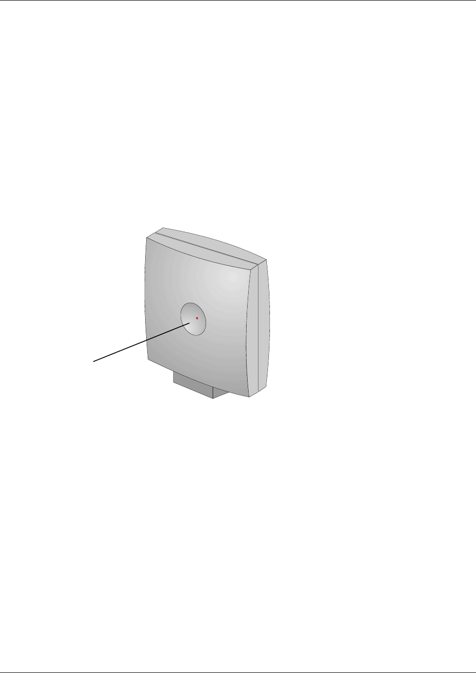
Figure 13 Isometric View of KIRK Repeater
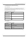
5.3.4 KIRK Repeater LED Indicators
The KIRK Repeater connection panel has one LED indicator describing the repeater faults and
failures. The indicator is off when the KIRK Repeater is not powered. The LED flashes when the
KIRK Repeater initializes. The indicator is on when the KIRK Repeater is operating.
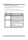
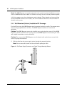
5.4 Installing the KIRK Repeater
The KIRK Wireless Server 600v3 is suitable for mounting indoors on a wall or ceiling.
Note: Before beginning the installation, determine the position of the repeater for best coverage.
The coverage depends on the construction of the building, architecture, and the choice of building
materials. Refer to
“Environmental Requirements” on page 27 for more information about
environmental requirements for repeaters.
Note: The KIRK Repeater does not add channels, it only adds additional coverage area.
LED