


4 Replacement Procedures
4-iv PORTEGE A200 Maintenance Manual (960-499)
4.19 SD board/System board .....................................................................................4-38
4.19.1 SD board.......................................................................................4-38
4.19.2 System board ................................................................................4-39
4.20 Heat sink/CPU....................................................................................................4-40
4.20.1 Heat sink.......................................................................................4-40
4.20.2 CPU..............................................................................................4-42
4.21 LCD mask/FL inverter/LED board....................................................................4-44
4.22 LCD unit ............................................................................................................4-48
4.23 LCD cable/LED cable ........................................................................................4-51
4.23.1 LCD cable.....................................................................................4-51
4.23.2 LED cable.....................................................................................4-54
4.24 Wireless LAN antenna .......................................................................................4-56
4.25 Hinge assembly..................................................................................................4-58
4.26 Fluorescent lamp................................................................................................4-60
4.26.1 Replacing the 12.1 inch TDM fluorescent lamp ..........................4-61
Figures
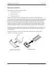
Figure 4-1 Removing the battery pack .........................................................................4-8
Figure 4-2 Installing a battery pack..............................................................................4-9
Figure 4-3 Removing the PC card ..............................................................................4-10
Figure 4-4 Removing the SD memory card ...............................................................4-11
Figure 4-5 Removing the connector panel.................................................................4-12
Figure 4-6 Removing the keyboard holder.................................................................4-13
Figure 4-7 Removing the keyboard (1)......................................................................4-14
Figure 4-8 Removing the keyboard (2)......................................................................4-15
Figure 4-9 Removing the optical drive (1) .................................................................4-16
Figure 4-10 Removing the optical drive (2) .................................................................4-17
Figure 4-11 Removing the screw .................................................................................4-18
Figure 4-12 Removing the palm rest ............................................................................4-19
Figure 4-13 Removing the touch pad ...........................................................................4-21
Figure 4-14 Removing the HDD assembly ..................................................................4-22